This thread has been locked.

If you have a related question, please click the "Ask a related question" button in the top right corner. The newly created question will be automatically linked to this question.

MMA Accelerometer Basic example

Other Parts Discussed in Thread: TMP100, PCF8574, DAC8571, MSP430G2553, MSP430WARE, ENERGIA

What I'm looking for is a very very basic working example code just to check the communication between a MSP430 and a MMA8652 accelerometer trough i2c pins. For example something that writes and read a register and nothing else, like a "Hello World".
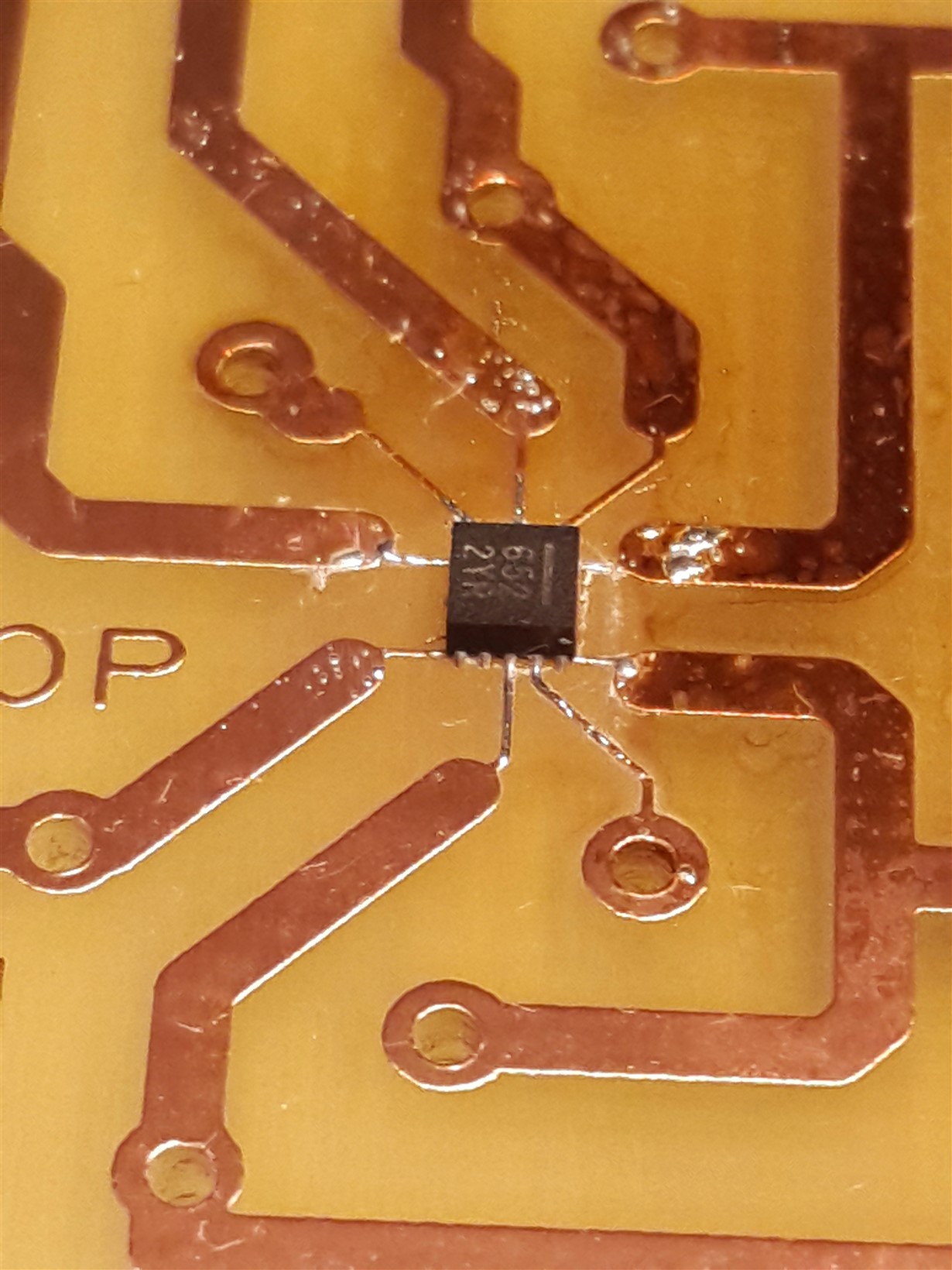
I have the MSP430 launchpad, the 8652 soldered in a board and I'm aware about i2c connections. I just need to verify that the 8652 is "alive".
Please help, thanks.


  • Hi Petrus!

    Don't know which launchpad you are using. Look here:

    There are code examples for the G2553 - especially for using I²C there are:

    • msp430g2xx3_uscib0_i2c_01.c                USCI_B0 I2C Master to TMP100, Set P1.0 if Temp > 28C
    • msp430g2xx3_uscib0_i2c_02.c                USCI_B0 I2C Master Interface to PCF8574, Read/Write
    • msp430g2xx3_uscib0_i2c_03.c                USCI_B0 I2C Master Interface to DAC8571, Write
    • msp430g2xx3_uscib0_i2c_04.c                USCI_B0 I2C Master RX single bytes from MSP430 Slave
    • msp430g2xx3_uscib0_i2c_05.c                USCI_B0 I2C Slave TX single bytes to MSP430 Master
    • msp430g2xx3_uscib0_i2c_06.c                USCI_B0 I2C Master TX single bytes to MSP430 Slave
    • msp430g2xx3_uscib0_i2c_07.c                USCI_B0 I2C Slave RX single bytes from MSP430 Master
    • msp430g2xx3_uscib0_i2c_08.c                USCI_B0 I2C Master TX multiple bytes to MSP430 Slave
    • msp430g2xx3_uscib0_i2c_09.c                USCI_B0 I2C Slave RX multiple bytes from MSP430 Master
    • msp430g2xx3_uscib0_i2c_10.c                USCI_B0 I2C Master RX multiple bytes from MSP430 Slave
    • msp430g2xx3_uscib0_i2c_11.c                USCI_B0 I2C Slave TX multiple bytes to MSP430 Master
    • msp430g2xx3_uscib0_i2c_12.c                USCI_B0 I2C Master TX/RX multiple bytes from MSP430 Slave with a repeated start in between TX and RX operations.
    • msp430g2xx3_uscib0_i2c_13.c                USCI_B0 I2C Slave RX/TX multiple bytes to MSP430 Master

    These will help you to establish a connection. Of course you will have to go through the datasheet of the MMA8652 to figure out how to address the device and it's registers.

    Dennis

  • Dennis, thank you for the information, I'll try to reformulate my question.
    You asked about my launchpad, it is a MSP-EXP430G2, with a MSP430G2553.
    From the list you gave me, I used this example: msp430g2xx3_uscib0_i2c_01.
    Forget the accelerator, in order to simplify the problem, I didn't connect any i2c device to the launchpad, I've just connected two 4.7K pull-up resistors from SCL to VCC and SDA to VDD. And I've removed P1.6 led jumper to avoid disturbances over SCL line.
    As I understand, this example should try to read repeatedly through i2c interface, regardless if there is a i2c device connected or not, it's that true?
    So I've connected the oscilloscope to the SCL and SDA lines, expecting to see some pulses but... nothing happens, SCL remains low and SDA remains high. The program seems not to be iterating. I copy the code below.
    Please I would like to know if this is a valid way to verify that the MCU is executing i2c actions. It is my first experience with i2c and I want to get a "Hello World" feedback to know that it works.
    Thanks.
    Pedro


    *******************************************************************************
    *
    * MSP430 CODE EXAMPLE DISCLAIMER
    *
    * MSP430 code examples are self-contained low-level programs that typically
    * demonstrate a single peripheral function or device feature in a highly
    * concise manner. For this the code may rely on the device's power-on default
    * register values and settings such as the clock configuration and care must
    * be taken when combining code from several examples to avoid potential side
    * effects. Also see www.ti.com/grace for a GUI- and www.ti.com/msp430ware
    * for an API functional library-approach to peripheral configuration.
    *
    * --/COPYRIGHT--*/
    //******************************************************************************
    // MSP430G2xx3 Demo - USCI_B0 I2C Master to TMP100, Set P1.0 if Temp > 28C
    //
    // Description: I2C interface to TMP100 temperature sensor in 9-bit mode.
    // Timer_A CCR0 interrupt is used to wake up and read the two bytes of
    // the TMP100 temperature register every 62ms. If the temperature is greater
    // than 28C, P1.0 is set, else reset. CPU is operated in LPM0. I2C speed
    // is ~100kHz.
    // ACLK = n/a, MCLK = SMCLK = TACLK = BRCLK = default DCO = ~1.2MHz
    //
    // /|\ /|\ /|\
    // | TMP100 10k 10k MSP430G2xx3
    // | ------- | | -------------------
    // +--|Vcc SDA|<-|---+->|P1.7/UCB0SDA XIN|-
    // | | | | | |
    // +--|A1,A0 | | | XOUT|-
    // | | | | |
    // +--|Vss SCL|<-+------|P1.6/UCB0SCL P1.0|---> LED
    // \|/ ------- | |
    //
    // D. Dang
    // Texas Instruments Inc.
    // February 2011
    // Built with CCS Version 4.2.0 and IAR Embedded Workbench Version: 5.10
    //******************************************************************************
    #include <msp430.h>

    unsigned int RxByteCtr;
    unsigned int RxWord;

    int main(void)
    {
    WDTCTL = WDTPW + WDTHOLD; // Stop WDT
    P1DIR |= BIT0; // P1.0 output
    P1SEL |= BIT6 + BIT7; // Assign I2C pins to USCI_B0
    P1SEL2|= BIT6 + BIT7; // Assign I2C pins to USCI_B0
    UCB0CTL1 |= UCSWRST; // Enable SW reset
    UCB0CTL0 = UCMST + UCMODE_3 + UCSYNC; // I2C Master, synchronous mode
    UCB0CTL1 = UCSSEL_2 + UCSWRST; // Use SMCLK, keep SW reset
    UCB0BR0 = 12; // fSCL = SMCLK/12 = ~100kHz
    UCB0BR1 = 0;
    UCB0I2CSA = 0x4e; // Set slave address
    UCB0CTL1 &= ~UCSWRST; // Clear SW reset, resume operation
    IE2 |= UCB0RXIE; // Enable RX interrupt
    TACTL = TASSEL_2 + MC_2; // SMCLK, contmode

    while (1)
    {
    RxByteCtr = 2; // Load RX byte counter
    UCB0CTL1 |= UCTXSTT; // I2C start condition
    __bis_SR_register(CPUOFF + GIE); // Enter LPM0, enable interrupts
    // Remain in LPM0 until all data
    // is RX'd

    if (RxWord < 0x1d00) // >28C?
    P1OUT &= ~0x01; // No, P1.0 = 0
    else
    P1OUT |= 0x01; // Yes, P1.0 = 1

    __disable_interrupt();
    TACCTL0 |= CCIE; // TACCR0 interrupt enabled
    __bis_SR_register(CPUOFF + GIE); // Enter LPM0, enable interrupts
    // Remain in LPM0 until TACCR0
    // interrupt occurs
    TACCTL0 &= ~CCIE; // TACCR0 interrupt disabled
    }
    }

    #if defined(__TI_COMPILER_VERSION__) || defined(__IAR_SYSTEMS_ICC__)
    #pragma vector = TIMER0_A0_VECTOR
    __interrupt void TA0_ISR(void)
    #elif defined(__GNUC__)
    void __attribute__ ((interrupt(TIMER0_A0_VECTOR))) TA0_ISR (void)
    #else
    #error Compiler not supported!
    #endif
    {
    __bic_SR_register_on_exit(CPUOFF); // Exit LPM0
    }

    // The USCIAB0TX_ISR is structured such that it can be used to receive any
    // 2+ number of bytes by pre-loading RxByteCtr with the byte count.
    #if defined(__TI_COMPILER_VERSION__) || defined(__IAR_SYSTEMS_ICC__)
    #pragma vector = USCIAB0TX_VECTOR
    __interrupt void USCIAB0TX_ISR(void)
    #elif defined(__GNUC__)
    void __attribute__ ((interrupt(USCIAB0TX_VECTOR))) USCIAB0TX_ISR (void)
    #else
    #error Compiler not supported!
    #endif
    {
    RxByteCtr--; // Decrement RX byte counter

    if (RxByteCtr)
    {
    RxWord = (unsigned int)UCB0RXBUF << 8; // Get received byte
    if (RxByteCtr == 1) // Only one byte left?
    UCB0CTL1 |= UCTXSTP; // Generate I2C stop condition
    }
    else
    {
    RxWord |= UCB0RXBUF; // Get final received byte,
    // Combine MSB and LSB
    __bic_SR_register_on_exit(CPUOFF); // Exit LPM0
    }
    }
  • Hi Dennis,
    I solved my problem, it was hardware trouble. Your examples were very useful to the trials. In order to go ahead, I would like to ask you to recommend me a I2C library which works with MSP4302553 and Code Composer Studio.
    I heard about "TI_USCI_I2C_master.h", but I couldn't find it to download, actually I've found different things under this name so I dont' know which is the correct one.
    Please if possible let me know if that library is suitable for my 2553 and CCS, and where can I find it.
    Thanks.
    Petrus
    Should I start this subject in a new thread?
  • Dennis, please read my last post about I2C library, which I mistakenly addressed to myself.
    Thanks. Petrus
  • Dennis, I've been doing a lot of trials last weeks, but I'm stuck with this.

    The only way I've been able to comunicate the MSP2553 to a MMA8652 accelerometer was using an Arduino code sample for Energia which I copy at the end, so I know the hardware is ok.

    The thing is I have a TI launchpad, and ai work with CCS; I've imported this Arduino code into CCS, and works, but it include a lot of librarys and the program becomes giant and difficult to control.

    I tried to adapt the USCI_B0 examples that comes with CCS but nothing, I cannot read a register, the result is always 0.

    And I worked with TI_USCI_I2C master library, also without success.

    ¿...? Really don't know what else to do. Is hard to believe that there is no example in the web to communicate a MSP430G2553 to a MMA8652.

    Dennis or anyone, please help.

    Best regards.

    ______________________________________________________________________________________________________________

    Energía working code

    #include <Wire.h>

    // I2C BUS:  already defined in "wire" librairy

    // SDA: PIN 2 with pull up 4.7K to 3.3V on arduino Micro

    // SCL: PIN 3 with pull up 4.7K to 3.3V on arduino Micro

    // Accelerometer connected to +3.3V of arduino DO NOT CONNECT TO 5V (this will destroy the accelerometer!)

    // all GND Pin of accelerometer connected to gnd of arduino

    /********************ACCELEROMETER DATAS************/

    // adresss of accelerometer

    int adress_acc=0X1D; // MMA8653FC and MMA8652FC

    // adress of registers for MMA8653FC

    int ctrl_reg1 = 0x2A;

    int ctrl_reg2 = 0x2B;

    int ctrl_reg3 = 0x2C;

    int ctrl_reg4 = 0x2D;

    int ctrl_reg5 = 0x2E;

    int int_source = 0x0C;

    int status_ = 0x00;

    int f_setup = 0x09;

    int out_x_msb = 0x01;

    int out_y_msb = 0x03;

    int out_z_msb = 0x05;

    int sysmod = 0x0B;

    int xyz_data_cfg = 0x0E;

    /******PROGRAM DATAS**********/

    int result [3];

    int axeXnow ;

    int axeYnow ;

    int axeZnow ;

    void setup(){

     Wire.begin(); // start of the i2c protocol

     Serial.begin(9600);  // start serial for output

     ACC_INIT(); // initialize the accelerometer by the i2c bus. enter the sub to adjust the range (2g, 4g, 8g), and the data rate (800hz to 1,5Hz)

    }

    //------------------------------------------------------------------

    void loop()

    {

    I2C_READ_ACC(0x00); // to understand why 0x00 and not 0x01, look at the data-sheet p.19 or on the comments of the sub. This is valid only becaus we use auto-increment    

    // NOTE: This communication is taking a little less than 1ms to be done. (for data-rate calculation for delay)

           Serial.print(axeXnow);

           Serial.print(";");

           Serial.print(axeYnow);

           Serial.print(";");

           Serial.print(axeZnow);

           Serial.print(";");

           Serial.println();

    delay(50);

    }

    //------------------------------------------------------------------

    void ACC_INIT()

    {

       I2C_SEND(ctrl_reg1 ,0X00); // standby to be able to configure

       delay(10);

       I2C_SEND(xyz_data_cfg ,B00000000); // 2G full range mode

       delay(1);

    //   I2C_SEND(xyz_data_cfg ,B00000001); // 4G full range mode

    //   delay(1);

    //   I2C_SEND(xyz_data_cfg ,B00000010); // 8G full range mode

    //   delay(1);

       I2C_SEND(ctrl_reg1 ,B00000001); // Output data rate at 800Hz, no auto wake, no auto scale adjust, no fast read mode

       delay(1);

    //   I2C_SEND(ctrl_reg1 ,B00100001); // Output data rate at 200Hz, no auto wake, no auto scale adjust, no fast read mode

    //   delay(1);

    //   I2C_SEND(ctrl_reg1 ,B01000001); // Output data rate at 50Hz, no auto wake, no auto scale adjust, no fast read mode

    //   delay(1);

    //   I2C_SEND(ctrl_reg1 ,B01110001); // Output data rate at 1.5Hz, no auto wake, no auto scale adjust, no fast read mode

    //   delay(1);    

    }

    //------------------------------------------------------------------

    void I2C_SEND(unsigned char REG_ADDRESS, unsigned  char DATA)  //SEND data to MMA7660

    {

     Wire.beginTransmission(adress_acc);

     Wire.write(REG_ADDRESS);

     Wire.write(DATA);

     Wire.endTransmission();

    }

    //------------------------------------------------------------------

    void I2C_READ_ACC(int ctrlreg_address) //READ number data from i2c slave ctrl-reg register and return the result in a vector

    {

     byte REG_ADDRESS[7];

     int accel[4];

     int i=0;

     Wire.beginTransmission(adress_acc); //=ST + (Device Adress+W(0)) + wait for ACK

     Wire.write(ctrlreg_address);  // store the register to read in the buffer of the wire library

     Wire.endTransmission(); // actually send the data on the bus -note: returns 0 if transmission OK-

     Wire.requestFrom(adress_acc,7); // read a number of byte and store them in wire.read (note: by nature, this is called an "auto-increment register adress")

     for(i=0; i<7; i++) // 7 because on datasheet p.19 if FREAD=0, on auto-increment, the adress is shifted

     // according to the datasheet, because it's shifted, outZlsb are in adress 0x00

     // so we start reading from 0x00, forget the 0x01 which is now "status" and make the adapation by ourselves

     //this gives:

     //0 = status

     //1= X_MSB

     //2= X_LSB

     //3= Y_MSB

     //4= Y_LSB

     //5= Z_MSB

     // 6= Z_LSB

     {

     REG_ADDRESS[i]=Wire.read(); //each time you read the write.read it gives you the next byte stored. The couter is reset on requestForm

    }

    // MMA8653FC gives the answer on 10bits. 8bits are on _MSB, and 2 are on _LSB

    // this part is used to concatenate both, and then put a sign on it (the most significant bit is giving the sign)

    // the explanations are on p.14 of the 'application notes' given by freescale.

         for (i=1;i<7;i=i+2)

         {

         accel[0] = (REG_ADDRESS[i+1]|((int)REG_ADDRESS[i]<<8))>>6; // X

           if (accel[0]>0x01FF) {accel[1]=(((~accel[0])+1)-0xFC00);} // note: with signed int, this code is optional

           else {accel[1]=accel[0];} // note: with signed int, this code is optional

               switch(i){

               case 1: axeXnow=accel[1];

                                 break;

               case 3: axeYnow=accel[1];

                                 break;

                case 5: axeZnow=accel[1];

                                 break;

                   }

          }

    }

    //------------------------------------------------------------------

    void I2C_READ_REG(int ctrlreg_address) //READ number data from i2c slave ctrl-reg register and return the result in a vector

    {

     unsigned char REG_ADDRESS;

     int i=0;

     Wire.beginTransmission(adress_acc); //=ST + (Device Adress+W(0)) + wait for ACK

     Wire.write(ctrlreg_address);  // register to read

     Wire.endTransmission();

     Wire.requestFrom(adress_acc,1); // read a number of byte and store them in write received

    }

  • This is another trial, I've adapted a code from an example in the web. It executes until the end apparently ok, but the reading result "PRxData" is always 00. I tried different variations over this code but nothing. I feel it is quite close, but something is still wrong.

    ________________________________________________________________________________________________________________

    #include <msp430g2553.h>


    int ctrl_reg1 = 0x2A;
    int lcount = 0;
    int TXByteCtr;
    unsigned char palout;
    unsigned char PRxData;
    int Rx = 0;
    char WHO_AM_I = 0x0D; //WHO_AM_I register address

    char itgAddress = 0x1D;

    void init_I2C(void);
    void Transmit(void);
    void Receive(void);


    int main(void)
    {
    WDTCTL = WDTPW + WDTHOLD; // Stop WDT
    P1SEL |= BIT6 + BIT7; // Assign I2C pins to USCI_B0
    P1SEL2|= BIT6 + BIT7; // Assign I2C pins to USCI_B0


    init_I2C();


    // while(1){
    //Transmit process
    Rx = 0;
    TXByteCtr = 1;
    palout= ctrl_reg1;
    Transmit();
    _delay_cycles(100);


    //Transmit process
    Rx = 0;
    TXByteCtr = 1;
    palout= itgAddress;
    Transmit();
    _delay_cycles(100);

    //Transmit process
    Rx = 0;
    TXByteCtr = 1;
    palout= 0x01;
    Transmit();
    _delay_cycles(100);


    //Receive process
    Rx = 1;
    Receive();
    lcount++;
    while(1);

    //}
    }

    //-------------------------------------------------------------------------------
    // The USCI_B0 data ISR is used to move received data from the I2C slave
    // to the MSP430 memory. It is structured such that it can be used to receive
    //-------------------------------------------------------------------------------
    #pragma vector = USCIAB0TX_VECTOR
    __interrupt void USCIAB0TX_ISR(void)
    {
    if(Rx == 1){ // Master Recieve?
    PRxData = UCB0RXBUF; // Get RX data
    lcount++;
    __bic_SR_register_on_exit(CPUOFF); // Exit LPM0
    }

    else{ // Master Transmit
    if (TXByteCtr) // Check TX byte counter
    {
    UCB0TXBUF = palout; // Load TX buffer
    TXByteCtr--; // Decrement TX byte counter
    }
    else
    {
    UCB0CTL1 |= UCTXSTP; // I2C stop condition
    IFG2 &= ~UCB0TXIFG; // Clear USCI_B0 TX int flag
    __bic_SR_register_on_exit(CPUOFF); // Exit LPM0
    }
    }

    }
    void init_I2C(void) {
    UCB0CTL1 |= UCSWRST; // Enable SW reset
    UCB0CTL0 = UCMST + UCMODE_3 + UCSYNC; // I2C Master, synchronous mode
    UCB0CTL1 = UCSSEL_2 + UCSWRST; // Use SMCLK, keep SW reset
    UCB0BR0 = 12; // fSCL = SMCLK/12 = ~100kHz
    UCB0BR1 = 0;
    UCB0I2CSA = itgAddress; // Slave Address is 069h
    UCB0CTL1 &= ~UCSWRST; // Clear SW reset, resume operation
    IE2 |= UCB0RXIE + UCB0TXIE; //Enable RX and TX interrupt
    }

    void Transmit(void){
    while (UCB0CTL1 & UCTXSTP); // Ensure stop condition got sent
    UCB0CTL1 |= UCTR + UCTXSTT; // I2C TX, start condition
    __bis_SR_register(CPUOFF + GIE); // Enter LPM0 w/ interrupts
    }
    void Receive(void){
    while (UCB0CTL1 & UCTXSTP); // Ensure stop condition got sent
    UCB0CTL1 &= ~UCTR ; // Clear UCTR
    UCB0CTL1 |= UCTXSTT; // I2C start condition
    while (UCB0CTL1 & UCTXSTT); // Start condition sent?
    UCB0CTL1 |= UCTXSTP; // I2C stop condition
    __bis_SR_register(CPUOFF + GIE); // Enter LPM0 w/ interrupts
    }
  • Well, after trying lots of samples in the web, I finally adapted my own example. It works well with MSP430G2553 + MMA8652 working with Code Composer Studio.

    It is a loop that reads the WHO_AM_I register content performing repeated start, the result is 4A for this accelerometer. As the operation is continuosly repeated, it is well suited to trace the variables and registers into CCS debug, and also to watch the signals in the oscilloscope.

    Sometimes when you run the program, the i2c communication appears as "hunged", so it is necessary to disconnect and connect the accelerometer after each time you build the project and before clicking start, into CCS. This is because I don't know a way to reset the accelerometer yet.

    Regards.

    Petrus

    _______________________________________________________________________

    #include <msp430g2553.h>
    
    char MMA8652_add = 0x1D;	//MMA8652 slave address
    char WHO_AM_I = 0x0D; 		//WHO_AM_I register address
    int lcount = 0;  		//Loop counter for debugging purposes
    char tx_byte;			//Byte to transmit
    char rx_byte;			//Byte to receive
    int Rx = 0;			//Flag for receive or transmit
    int TXByteCtr;			//Flag to indicate there is a byte to send
    
    int main(void) {
    	WDTCTL = WDTPW + WDTHOLD;               // Stop WDT
    
    	// I2C Inicialization
    	P1SEL |= BIT6 + BIT7;                   // Assign I2C pins to USCI_B0
    	P1SEL2 |= BIT6 + BIT7;                  // Assign I2C pins to USCI_B0
    	UCB0CTL1 |= UCSWRST; 					// Enable SW reset
    	UCB0CTL0 = UCMST + UCMODE_3 + UCSYNC; 	// I2C Master, synchronous mode
    	UCB0CTL1 = UCSSEL_2 + UCSWRST; 			// Use SMCLK, keep SW reset
    	UCB0BR0 = 50; 							// fSCL = SMCLK/50
    	UCB0BR1 = 0;
    	UCB0I2CSA = MMA8652_add; 				// Setting slave address
    	UCB0CTL1 &= ~UCSWRST; 					// Clear SW reset, resume operation
    	_delay_cycles(5000);
    	while (1) {
    		Rx = 0;
    		TXByteCtr = 1;
    		tx_byte = WHO_AM_I;
    		UCB0CTL1 |= UCTR + UCTXSTT; 		// I2C TX, start condition
    		IE2 |= UCB0TXIE; 					//Enable TX interrupt
    		__bis_SR_register(LPM4_bits + GIE);     // Enter LPM0 w/ interrupts
    		while (UCB0CTL1 & UCTXSTP); 		// Check stop sent
    		lcount++;   			        // To see into CSS variables that the loop is working
    		_delay_cycles(500);
    	}
    }
    
    // USCI_B0 data ISR
    #pragma vector = USCIAB0TX_VECTOR
    __interrupt void USCIAB0TX_ISR(void) {
    	if ((IFG2 & UCB0TXIFG) || (IFG2 & UCB0RXIFG)) //Interrupt was triggered by a RX or TX event?
    		{
    		if (Rx == 1) { 					//Receive
    			rx_byte = UCB0RXBUF; 			//Move RX data to variable
    			while (UCB0CTL1 & UCTXSTT); 		//Wait until acknowlege
    			UCB0CTL1 |= UCTXSTP; 			// No Repeated Start: stop condition
    			IE2 &= ~UCB0RXIE; 			//Disable Rx int
    			__bic_SR_register_on_exit(LPM4_bits); 	// Exit LPM0
    
    		}
    
    		else { 					// Rx=0 - Transmit
    			if (TXByteCtr) 			// If there is a tx_byte to transmit
    			{
    				UCB0TXBUF = tx_byte; 	// Load TX buffer
    				TXByteCtr = 0;		// No tx_byte to transmit next time
    			} else {			// If the tx_byte has already been transmitted
    				IFG2 &= ~UCB0TXIFG; 	// Clear USCI_B0 TX int flag
    				IE2 &= ~UCB0TXIE; 	//Disable TX interrupt
    				Rx = 1;			//Next is a read
    				UCB0CTL1 &= ~UCTR; 	//Sets the master as a receiver
    				UCB0CTL1 |= UCTXSTT; 	//Start Condition sends address of slave
    				IE2 |= UCB0RXIE;	//Enable RX interrupt
    			}
    		}
    	}
    }
    

  • "I don't know a way to reset the accelerometer yet."
    If it doesn't have a reset pin, you might control its supply voltage by an MSP port pin. E.g. a P-channel FET between supply and VCC, controlled by an MSP port pin.
    Of course it would be better to figure out what makes the slave choke. You can try to simulate a stop condition on the I2C pins using GPIO, before switching them over to USCI mode. Maybe that's enough (previous transfer interrupted during ongoing transfer, so the slave is still busy sending to a master that doesn't listen)
    A logic analyzer would tell where it hangs.

**Attention** This is a public forum