This thread has been locked.

If you have a related question, please click the "Ask a related question" button in the top right corner. The newly created question will be automatically linked to this question.

msp430 i2c problems

Other Parts Discussed in Thread: MSP430G2553, PCF8574

Hi,

I wrote the following code:

#include <msp430.h> 

/*
* main.c
*/
signed char size;
unsigned char *dataReceive;
unsigned char *dataTransmit;

unsigned char slaveAddr = 0x20;
int main(void) {
WDTCTL = WDTPW | WDTHOLD; // Stop watchdog timer
P1SEL |= BIT7 + BIT6; // SET SDA + SCL Functions
P1SEL2 |= BIT7 + BIT6; // SET SDA + SCL Functions
UCB0CTL1 |= UCSWRST; //reset
UCB0CTL0 |= UCMST + UCMODE_3 + UCSYNC; // I2C SYNC MASTER MODE
UCB0BR0 = 0x08;
UCB0BR1 = 0;
UCB0I2CSA = slaveAddr;
UCB0CTL1 |= UCSSEL_3 + UCSWRST; // SMCLK
UCB0CTL1 &= ~UCSWRST; //resume operation
UCB0I2CIE |= UCNACKIE;
IE2 |= UCB0TXIE + UCB0RXIE; // Enable TX & RX interrupt
dataTransmit = "Hello";
size = 5;

while(UCB0STAT & UCBBUSY);//waiting for master stop being busy
UCB0CTL1 |= UCTR + UCTXSTT; // set transmitter and start condition
__bis_SR_register(GIE);
while(1){
}
return 0;
}


#pragma vector = USCIAB0RX_VECTOR
__interrupt void USCIAB0RX_ISR(void)
{
if (UCB0STAT & UCNACKIFG){ // send STOP if slave sends NACK
UCB0CTL1 |= UCTXSTP;
UCB0STAT &= ~UCNACKIFG;
}


}

#pragma vector = USCIAB0TX_VECTOR
__interrupt void USCIAB0TX_ISR(void)
{
if (IFG2 & UCB0RXIFG){
if ( size == 0 ){
UCB0CTL1 |= UCTXSTP; // I2C stop condition
*dataReceive = UCB0RXBUF;
dataReceive++;
}
else {
*dataReceive = UCB0RXBUF;
dataReceive++;
size--;
}
}
else {
if (size == 0){
UCB0CTL1 |= UCTXSTP; // I2C stop condition
IFG2 &= ~UCB0TXIFG; // Clear USCI_B0 TX int flag
}
else {
UCB0TXBUF = *dataTransmit;
dataTransmit++;
size--;
}
}
}

And i have those questions:

1.When i'm wiriting the lines:

P1SEL |= BIT7 + BIT6; // SET SDA + SCL Functions
P1SEL2 |= BIT7 + BIT6; // SET SDA + SCL Functions

the code is stuck in this line: while(UCB0STAT & UCBBUSY);
which means that the UCBBUSY bit is high.

but when i omit one of the P1SEL lines the code doesn't stuck ( UCBBUSY bit is low)

why this is happens?

2. after it passes the while "busy" loop it's running the interrupt event once which takes only one character and doesn't show it on the slave(lcd), i assume that the interrupt will run untill it get stop bit(UCTXSTP) and the flag is clear (UCB0TXIFG) but it doesn't

3. how to compute the smclk communication speed? i searched, but didn't find nothing.

The slave address is the correct address.

Thank you.

UPDATE:


the msp is msp430g2553 

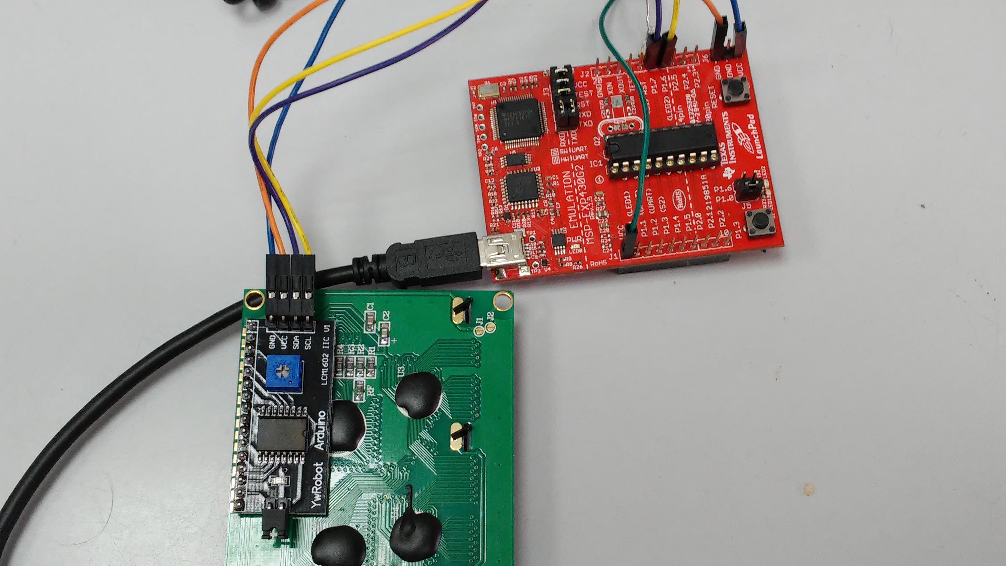
I'm attaching  an image of the circuit

blue  - vcc

orange - gnd

yellow -scl

purple - sda

green - vcc with 10k resistors for sda and scl

  • Which MSP? And show your circuit.
  • Hi thank you for the reply
    i update my question, please see above.
    Thank you for your help
  • How are the pull-up resistors connected?
  • they are parallel
    I mean same vcc but spliting one to the scl and the other to the sda
  • Can you measure the SDA/SCL lines with an oscilloscope or logic analyzer? Or at least a multimeter?

  • Yes, I've checked with multimeter

    General Voltage 3.7V

    and both sda and scl 3.7V

  • You should use a supply voltage that is actually allowed.

    I don't know why UCBBUSY is set; in theory, this should not be possible directly after the reset.
  • Hi,
    After you said you don't know why UCBBUSY is set, i assumed something wrong with the launchpad so i took another and suddnely it's not busy anymore and it looks like it's working but, i don't see the characters on the lcd.
    what do i need to investigate to see the results?
  • This sounds as if the SCL pin of the old LaunchPad is broken. Probably overvoltage (the nominal upper limit is 3.3 V) or ESD.

    I doubt that you can simply send characters over I²C. Is there any documentation about the I²C protocol?
  • yes, i have documentation for i2c protocol on the following link: www.nxp.com/.../PCF8574.pdf
    the PCF8574 is the chip for the lcd's i2c controller(YWrobot)
    another thing i notice, the SCL line controls the rythm of the data transfer, so the voltage on it is changing (high to low, low to high) but i see that is always hi, i mean getting 3.7V everytime. i assume it needs to be ~2.5V (making an average) does it make any sense?
  • The PCF8574 is just an I/O expander. How are its 8 data pins connected to the LCD controller?
  • The lcd and the ywrobot (including PCF8574T expender) were bought from arduino so i'm pretty sure that the 8 data pins are connected correctly to the lcd, more over i ran the code with 2 more lcd (the same product) but i got the same result.
  • But which pins of the PCF8574 are connected to which pins of the HD44780?
  • if i understand correctly this is how they are connected:

    p0 in pcf8574t is connected to rs in lcd
    p1 in pcf8574t is connected to rw in lcd
    p2 in pcf8574t is connected to e in lcd
    p4 in pcf8574t is connected to d4 in lcd
    p5 in pcf8574t is connected to d5 in lcd
    p6 in pcf8574t is connected to d6 in lcd
    p7 in pcf8574t is connected to d7 in lcd

    i don't see nothing connected to d0-d3
  • You cannot simply send characters over I²C; you have to send command and data bytes to the HD44780 using the correct protocol, and to configure it first. Even Wikipedia explains it.

  • How do you know that the lcd is HD44780?

    I followed the instructions at: fab.cba.mit.edu/.../44780.pdf page 40
    In the code i'v changed the following(Which need to display "H"):

    dataTransmit = "\x30\x0E\x06\x248";
    size = 4;

    but still get no answer and the screen of the lcd is turned off and when i set the stop bit it turns on

    maybe i need some delay between characters?
  • That string contains five bytes. And D0..D3 are not connected, so you must use 4-bit mode. And you are not handling the RS/RW/E pins.
  • what is the fifth byte? is it the null in the end of the string?
    and how can i handle rs/rw/e pins from the msp430?
    I thought that 248 in binary is 1001001000 and the first bit (from the left) is the rs and the second bit is the rw

    when i look at the 4-bit mode example in the pdf on page 42 i see that it sends zero(like null) and it cut my string
  • "\x24" is the fourth byte, "8" the fifth.

    With the I/O expander, you have only 8 bits.

    To write to the LCD controller, you have to first set the data bits and RS/RW bits to their desired values, and E to 1, and then you have set E to 0. (It is the falling edge of E that causes the controller to act on its inputs.)

    To write a byte, you have to write 4 bits, twice. (Except at the beginning, where you are in 8-bit mode.)

    To write a command byte with bits HGFEDCBA, you have to write HGFE0100, HGFE0000, DCBA0100, DCBA0000.
    To write a data byte with bits HGFEDCBA, you have to write HGFE0101, HGFE0001, DCBA0101, DCBA0001.

  • If i understand correctly
    I need first to set RS to 0 for Initialise the display and set entry mode for example: 000000110 (this is for setting Entry Mode, Increment cursor position, No display shift) when the first 0 from the left is the RS
    and then set the RS to 1 for sending characters for example the letter H: 101001000 when the first 1 from the left is the RS
    I assume that E is incharge of the clock?

    In the code, i don't know how to set the RS and The E bits (the RW i set in UCTR that means it's transmitting)
    the E is not the SMCLK and UCB0BR combination?

    I new to all of this.
    Thank you for your patience
  • When you send a byte over I²C, you set the outputs of the PCF8574. In every sent byte, the bits are D7 D6 D5 D4 0 E RW RS.

    SMCLK and UCBxBR set the speed of the I²C communication; this has nothing to do with the interface between the PCF and the HD. UCTR specifies that you're transmitting on the I²C bus; this has nothing to do with the RW bit.

    To set E, send a byte with the value xxxxx1xx. To clear E, send a byte with the value xxxxx0xx. Similarly for all the other bits.

  • You need helper functions like this:

    void switchFrom8To4Bits()
    {
    	static unsigned char buf[2] = { 0x24, 0x20 };
    
    	dataTransmit = buf;
    	size = 2;
    	while(UCB0STAT & UCBBUSY);
    	UCB0CTL1 |= UCTR + UCTXSTT;
    }
    
    void write2x4Bits(unsigned char bits, int is_data)
    {
    	static unsigned char buf[4];
    
    	buf[0] = (bits & 0xf0) | is_data | 0x04;
    	buf[1] = (bits & 0xf0) | is_data;
    	bits <<= 4;
    	buf[2] = (bits & 0xf0) | is_data | 0x04;
    	buf[3] = (bits & 0xf0) | is_data;
    
    	dataTransmit = buf;
    	size = 4;
    	while(UCB0STAT & UCBBUSY);
    	UCB0CTL1 |= UCTR + UCTXSTT;
    }
    
    void writeCommand(unsigned char command)
    {
    	write2x4Bits(command, 0);
    }
    
    void writeData(unsigned char data)
    {
    	write2x4Bits(command, 1);
    }
  • I think i made a good progress
    i'm sending 2 bytes(one when E is1 and the other when E is 0 like you mentioned)
    for example: i'm trying to display 9 (in the fab.cba.mit.edu/.../44780.pdf page 17 is 00111001) so i'm first byte i'm sending is: 00110101 (RS is 1 E is 1 and 0011 is the first four bits) and then i'm sending 10010001(RS is 1 E is 0 and last four bits) but the display show me a question mark and this is due to that question mark byte is: 00111111, it always takes the 1111 last bits how can i set the four last bits correctly

    Furthermore, i just want to say thank you for your patience and time you helped me a lot(you have no idea how much :) )
  • After reset, the controller is in 8-bit mode. You have to switch to 4-bit mode.
  • for setting 4-bit mode i need to send 00100000 (0x20) rs=0,e=0,db5=1.
    from the pdf file i need only to send this to set 4-bit mode but it is still not working
  • And how am I supposed to help you if you keep your source code secret?

    Is your code different from switchFrom8To4Bits()? If yes, why?
  • when i use switchFrom8To4Bits the lcd stop reacting i mean when i send 0x24 and then 0x20 but sending only 0x20 it doesn't get stuck just does nothing

    here's the code with the new functions you gave me:

    #include <msp430.h> 
    
    /*
     * main.c
     */
    signed char size;
    unsigned char *dataReceive;
    unsigned char *dataTransmit;
    
    unsigned char slaveAddr = 0X27;
    
    void switchFrom8To4Bits()
    {
        static unsigned char buf[2] = { 0x24, 0x20 };
    
        dataTransmit = buf;
        size = 2;
        while(UCB0STAT & UCBBUSY);
        UCB0CTL1 |= UCTR + UCTXSTT;
    }
    
    
    void write2x4Bits(unsigned char bits, int is_data)
    {
        static unsigned char buf[4];
    
        buf[0] = (bits & 0xf0) | is_data | 0x04;
        buf[1] = (bits & 0xf0) | is_data;
        bits <<= 4;
        buf[2] = (bits & 0xf0) | is_data | 0x04;
        buf[3] = (bits & 0xf0) | is_data;
    
        dataTransmit = buf;
        size = 4;
        while(UCB0STAT & UCBBUSY);
        UCB0CTL1 |= UCTR + UCTXSTT;
    }
    
    void writeCommand(unsigned char command)
    {
        write2x4Bits(command, 0);
    }
    
    void writeData(unsigned char data)
    {
        write2x4Bits(data, 1);
    }
    
    int main(void) {
        WDTCTL = WDTPW | WDTHOLD;	// Stop watchdog timer
    	P1SEL |= BIT7 + BIT6; // SET SDA + SCL Functions
    	P1SEL2 |= BIT7 + BIT6; // SET SDA + SCL Functions
    	UCB0CTL1 |= UCSWRST; //reset
    	UCB0CTL0 |= UCMST + UCMODE_3 + UCSYNC; // I2C SYNC MASTER MODE 10 BIT ADDRESS
    	UCB0BR0  = 0x08;
    	UCB0BR1  = 0;
    	UCB0I2CSA = slaveAddr;
    	UCB0CTL1 |= UCSSEL_3 + UCSWRST; // SMCLK
    	UCB0CTL1 &= ~UCSWRST; //resume operation
    	UCB0I2CIE |= UCNACKIE;
    	IE2 |= UCB0TXIE + UCB0RXIE;                      // Enable TX & RX interrupt
    
    	__bis_SR_register(GIE);
    
    	switchFrom8To4Bits();
    	writeCommand(0x04);
    	writeCommand(0x00);
    	writeData(0x55);
    	writeData(0x81);
    	/*dataTransmit ="\x04\x00\x55\x81";//"H";
    	size = 4;
    	while(UCB0STAT & UCBBUSY);//waiting for master stop being busy
    		UCB0CTL1 |= UCTR + UCTXSTT ; // set transmitter and start condition
    	__bis_SR_register(GIE);*/
    	while(1){
    	}
    	return 0;
    }
    
    
    #pragma vector = USCIAB0RX_VECTOR
    __interrupt void USCIAB0RX_ISR(void)
    {
      if (UCB0STAT & UCNACKIFG){            // send STOP if slave sends NACK
        UCB0CTL1 |= UCTXSTP;
        UCB0STAT &= ~UCNACKIFG;
      }
    
    
    }
    
    #pragma vector = USCIAB0TX_VECTOR
    __interrupt void USCIAB0TX_ISR(void)
    {
      if (IFG2 & UCB0RXIFG){
        if ( size == 0 ){
          UCB0CTL1 |= UCTXSTP;                    // I2C stop condition
          *dataReceive = UCB0RXBUF;
          dataReceive++;
        }
        else {
          *dataReceive = UCB0RXBUF;
          dataReceive++;
          size--;
        }
      }
      else if (IFG2 & UCB0TXIFG){
        if (size == 0){
          UCB0CTL1 |= UCTXSTP;                    // I2C stop condition
          IFG2 &= ~UCB0TXIFG;                     // Clear USCI_B0 TX int flag
        }
        else {
          UCB0TXBUF = *dataTransmit;
          _delay_cycles(250000);
          dataTransmit++;
          size--;
        }
      }
    }


  •     writeCommand(0x04);
        writeCommand(0x00);

    Command 0x04 (decrement, no shift) does not make sense, and there is no command 0x00.

    You forgot to switch on the display.

  • to show the display i need 2 lines of command one for the higher 4 bits and the second for the lower 4 bits in which the E is changed (first with 1 the second with 0)

    the higher fout bits are 0000 (db4-db7) and the lower bits are 1111 (because  i want to display to be on and to see cursor and the cursor blinks)

    so the first command will be: 00000100 (0x04) 

    the second  will be: 11110000(0xf0)

    so i added: 

    writeCommand(0x04);
    writeCommand(0xF0);

    but is not working this is what happens when i ran the  new code

  • Each four-bit transfer requires its own falling edge on E, so you need four I²C writes to transfer a single byte.

    The write2x4Bits function already takes care of this.

    To write the command 00001111, just call writeCommand(0x0F);
  • ok so i'm sending only this command writeCommand(0x0F); nothing else
    i should see the display turned on but it isn't turned on the cursor does blink when i ran it again from the computer the cursor disappear and when i ran it again (3rd time) it get stuck on the UCCBUSY of the switchFrom8To4Bits part but when i remove the 0x24 the cursor remains blinking
    in the pdf of the HD44780U page 42 they wrote: "Sets to 4-bit operation. In this case, operation is handled as 8 bits by initialization, and only this instruction completes with one write."

    and they show only one line.

    Furthermore, on page 45 they have an instructions to initialize but i failed to make it work
    I know you try to help and i'm very gratefull but i don't know what i'm missing to make it works.
  • Resetting the MSP does not reset the HD44780; to reliably initialize 4-bit mode, you need something like this:

    void switchFrom8To4Bits()
    {
        static unsigned char buf[8] = { 0x34, 0x30, 0x34, 0x30, 0x34, 0x30, 0x24, 0x20 };
    
        dataTransmit = buf;
        size = 8;
        while(UCB0STAT & UCBBUSY);
        UCB0CTL1 |= UCTR + UCTXSTT;
    }

    To initialize the LCD, you should use these commands:

    sendCommand(0x2F); // function set: 4-bit mode, 2 lines, 5x10 characters
    sendCommand(0x0F); // display on
    sendCommand(0x01); // display clear
    sendCommand(0x06); // entry mode

  • yes you right now it's working perfectly

    YOU ARE THE MAN (yes i'm shouting because i'm excited)

    thank you so much very so much

**Attention** This is a public forum