This thread has been locked.

If you have a related question, please click the "Ask a related question" button in the top right corner. The newly created question will be automatically linked to this question.

SD Card and SPI

Other Parts Discussed in Thread: MSP430F5438, MSP430F1611, MSP430F2370

Hi,

I am at wits end trying to figure out what I am doing wrong interfacing am MSP430F5438 with a 1 GB SD Card.  

I've checked that the clock is at 400 kHz, the CS line is at 0 Volts when asserted.

For UCB1CTL0 I've tried all combinations, but I'm mostly sure that UCCKPL is the correct configuration from this post:

http://e2e.ti.com/support/microcontrollers/msp43016-bit_ultra-low_power_mcus/f/166/p/37139/129769.aspx#129769


I've also read the foust app note and the SanDisk Secure Digital Card Product Manual Version 1.9.  Still can't figure it out.  It seems so simple to send 5 bytes over SPI and get the R1 responce, but the SD card remains silent. I've also replace my SD card with a new one.  


The following code doesn't show the boot up code, but my peripherals are configured correctly. I can see the clock and the MOSI signals on my scope, and they look correct to me.  I'm not sure what I did, but one time the SD card even started sending over data, but it didn't seem to be valid R1 responses, bu tnow I can't repeat that.  


Code is below, any troubleshooting advice would be greatly appreciated. 


WDTCTL = WDTPW + WDTHOLD; // disable watch dog for tesintg

UCB1CTL1 |=  UCSWRST; // **Put state machine in reset**

UCB1CTL1 |= UCSSEL__SMCLK; // select SMCLK

UCB1CTL0 =UCSYNC|  UCMST| UCMSB| UCCKPL;//  ;


// SET TO 400 KHZ

UCB1BR0 = 0x28;

UCB1BR1 = 0x0;

UCB1CTL1 &=  ~UCSWRST;   // **Initialize USCI state machine**

char tmp;

while (1)

{

spi_cs_assert();

//__delay_cycles(250000);

spi_send_byte((0x40));

spi_send_byte((0x00));

spi_send_byte((0x00));

spi_send_byte((0x00));

spi_send_byte((0x00));

spi_send_byte((0x95));

do

{

tmp = spi_rcv_byte();

i++;

}

while (((tmp & 0x80) != 0) && i < 100);

spi_cs_deassert();

__delay_cycles(250000);

}


/* Send a single byte over the SPI port */

void spi_send_byte(unsigned char input)

{

//IFG1 &= ~URXIFG0;

/* Send the byte */

unsigned char tmp;

/* Send the byte */

while ((UCB1STAT & UCBUSY)); // SPI ready?

while (!(UCB1IFG&UCTXIFG));           // USCI_B1 TX buffer ready?

UCB1TXBUF = input;

/* Wait for the byte to be sent */

//UCTXIFG is set when UCxxTXBUF empty.

while ((UCB1IFG & UCTXIFG) == 0) { }

}

/* Receive a byte. Output an 0xFF (the bus idles high) to receive the byte */

unsigned char spi_rcv_byte()

{

unsigned char tmp;

/* Send the byte */

tmp = UCB1RXBUF; // clear buffer

while ((UCB1STAT & UCBUSY)); // SPI ready?

spi_send_byte(0xFF);

/* Wait for the byte to be received */

while ((UCB1IFG & UCRXIFG) == 0) { }

while ((UCB1STAT & UCBUSY)); // SPI ready?

tmp = UCB1RXBUF;

return (tmp);

}

  • I guess your SMCLK is running at 16MHz? I guess so from teh clock divider of 40 :)

    My implementation of the SD card is dated back on the MSP430F1611, where it worked with 1GB cards. I never tested the ported code on the 5438 yet (the test board isn't finished). Anyway, are you sure that your card is not an SDHC card? It would be not necessary for 1GB, but then, the manufacturer could have done it as SDHC card for speed reasons or to sell the cards where part of the 4GB memory is defective :)

    Let's see. The init procedure is a bit tricky. If you don't get a response on the first run, start over. So you need a timeout and then try again until you got the response.

    First, before selecting the card, the card may need some SPI clock pulses. My init code sends 10 0xff bytes with the card NOT selected (CS de-asserted).

    The, CS is asserted and the GO_IDLE_STATE command (0x40) is sent.

    After this, my code sends up to 10 times 0xff and checks the data received in return. If the received value is <> 0xff, it is the response. It should be 0x01 for the idle command.

    next step is to de-assert CS and send another 0xff byte.

    After doing so (in my setup, 1ms has passed now, since it executs in 1ms timer interrupt context), the card is ready for access.

    Assert CS, then send APP_CMD (0x77). Wait for response. If R1_ILLEGAL_CMD bit (0x04) is set, it is an MMC card, else an SD card. De-assert CS.

    Assert CS. now send either  SEND_OP_COND (0x41, if it was an MMC card) or APP_SEND_OP_COND (0x69). Wait for response, de-assert CS.

    Now send another dummy byte with CS de-asserted. If the response was 0, the card is now ready to be operated at 20MHz. If it was 0x01, the card is still initializing: go back to the last step.

    I guess the main problem with your code was that you didn't send the dummy bytes before the first access of the card. So the card isn't ready to repond to anthing. I wonder why this is necessary at all, but maybe it is necessary to wakeup the controller from sleep and activate SPI mode. At least it doesn't work properly without these initial clock cycles. You'll find the neccessity of these superfluous cycles during normal device operation too, e.g. after writing a sector etc.

    Anyway, implementing byte read and byte write as functions isn't the most performant way. Way too much overhead.
    I wrote a set of macros which will be inlined into the code. If you clock the SPI with MCLK (which is possible on 54xx), you only have 8 clock cycles per byte if you don't want to have the bus sitting idle.
    I even didn't just implement byte read/byte write. Since you have to write a byte to read a byte, both is essentially the same macro. Send a byte and wait for the return value. But there's more:

    In case of block data transfer, I also wrote a set of macros to start a block transfer, transfer the next byte and then do the last byte. In case of write, the start just writes to TXBUF, the next waits for TXIFG set before writing the next and the last waits for the busy bit, ensuring the SPI is idle. For the read, it is a bit different, the start just sends a dummy byte, then the next macro waits for TXIFG and writes anothe rdummy, then waits for RXIFG and returns the result. With GIE clear (so no ISR can cause an RX overflow). The last macro just waits until the last byte was received. This has proven to result in the highest throughput.
    On the 1611 with a maximum SPI clock of 4MHz, I was able to read with ~390kB/s. On the 5438 wth 16MHz clock, it should be almost 4 times that much.

  • I vote for this Jens-Michael's post for immediate admittance to the "external posters - Hall of Fame!"

    Detailed, discerning (who knew about SDHC card's possible use), caring.

    To combine high-volume posts with such insight - and detail - is most unusual.   Your work IS appreciated!

  • Hi JWise, did you figure out the problem? Can you show us your code fixed? 

    Thanks!

  • Jens-Michael Gross said:
    My init code sends 10 0xff bytes with the card NOT selected (CS de-asserted) ...  I wonder why this is necessary at all, but maybe it is necessary to wakeup the controller from sleep and activate SPI mode

    Yes, that is exactly the purpose of it! It is precisely this sequence that wakes the card into SPI mode - as opposed to SD mode.

    See section 6.4.1, "Power Up" in the SD Specifications, Part 1, Physical Layer Simplified Specification; Version 3.01, May 18, 2010:

    6.4.1 Power Up

    The host shall supply power to the card so that the voltage is reached to Vdd_min within 250ms and start to supply at least 74 SD clocks to the SD card with keeping CMD line to high. In case of SPI mode, CS shall be held to high during 74 clock cycles.

    (my emphasis)

    https://www.sdcard.org/downloads/pls/simplified_specs/

  • Greetings,

    thanks for the detailed, clear exposition. I'd like to ask for some help.

    Problem description:

    I've built a MSP430F2370 based 15693 RFID tag reader/writer .
    The main board has a daughter board, shaped as a SD card,
    which connects to a SD card holder/reader. 

    We were planning to communicate with a Windows Mobile 6 handheld
    via  SD card interface using SPI. Our software team told us this was technically impossible,
    or at least would take a couple of months to implement. We got three weeks to finish all of it.

    So, the ball returned to me. Now I was asked to emulate a SD card
    with the MSP. This includes all the SPI communication and FAT16 emulation as well.
    This has been done before, afak not with a MSP though. 

    Question: 

    After some search here at the Community, I was unable to find previous works
    using MSPs to emulate SD cards. Is there any info/work done about it?
    Also,  I have a handfull of thick SD card specifications PDFs, but I can't seem
    to find timing diagrams telling what a happy SD card should send to a host. 
    If someone could also please address me to a more concise, good documentation on this, 
    it'd be very nice.

    Thank you all for the good work.
    Xezi 


  • The typical implementation is that thje MSP will try to access an SD card, not to pretend to be one.

    There ar emany reasons for this. One is that the MSP doesn't have enough memory to make this a useful approach. The biggest ones have 256k which in theory could be used for data storage. Providing virtual data would require lots of ram. The 2370 neither has any of them (ram/flash) in a significant amount.

    Second is the speed. SD cards have to operate on very high speeds. 20-25MHz clock speed are normal. If the MSP shall play the role of an SD card, it has to react with this speed. Which is almost impossible.

    Things are a bit more relaxed when using the SPI-like serial protocol. This is, however, MMC-card compliant. And there are many SD-card controllers (readers) which only accept the parallel SD protocol, not the serial one. (those readers which onyl read SD/SDHC but not MMC).

    With 16MHz CPU clock frequency, the MSP could be operating with up to 8MHz SPI clock speed. Still a very, very narrow timing. But doable. 16 CPU clock cycles per byte. It would require hand-crafted assembly code for the transfer functions as well as for receiving and handling the non-Data commands.

    To sum it up: it is possible but tricky and dificult, to simulate an MMC card (or SD card in MMC mode). But only at a limited clock frequency.
    And with only 2k Ram on the 2370, it's quite narrow to implement a filesystem driver. even though the 32k flash might be sufficient for some static content.

  • Thank you.

    We'll try to implant a micro SD card within the MSP hardware and use it bus wise. The MSP periodically breaks up the
    handheld - SD card connection via a tri-state line driver and accesses the card, writing data and giving the card back to the 
    handheld.

    Xezi 

  • Switching the SD host is a tricky thing. The handheld may assume the SD is in the state it left it.
    You should ensure that the 'switch' is recognized as removal and re-insertion of the card, or else you might encounter severe (and barely traceable) problems.
    Your MSP code may be able to cope with the problems of a 'context switch', but the handheld, which doesn't know about it happening, migh cough if the SD card has been accessed by someone else in the meantime.

  • You also need to be absolutely certain that the handheld is 101% safe against data loss and/or corruption in the event of "surprise" removal of the card...


  • Thanks.

    I've just read that "The Ti code works with SPI interface mode
    (which is the simplest choice of the three SD interface modes)
    which is not required to be supported by microSD cards".

    Is this true? Not all microSD implement SPI?

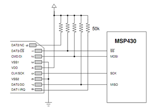
    Also, there is this diagram,

    telling that all data lines should be Vcc-ed by a 50k res, not only CS.
    Is this relevant? 

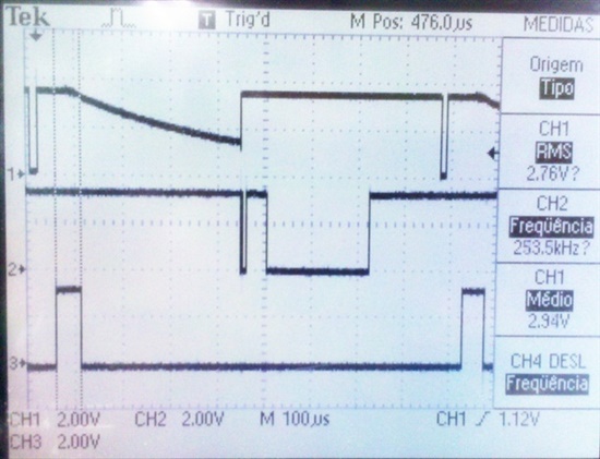
    I'm getting these signals for DO, DI and CS, using
    slaa281b code example (MSP-MMC demo v1.2):

     And the code is stuck with this call stack: main, mmcInit, mmcGoIdle, mmcSendCmd,
    apparently because the microSD is not polite enough to send anything different from 0x01,
    so the MSP430F2370 refuses to stablish a friendship with him.

    Now,  Jens-Michael Gross has already implemented this SD card communication,
    way back to the 1611. Was this implementation shared with the community? I was unable
    to find it. Also, the example code v1.2 has not worked properly, even after the obvious
    port/pins readdressing to my specific hardware. Maybe Gross' work works better?

    Thanks again,

    Xezi 

  • Bruno Marchesi said:

    Is this true? Not all microSD implement SPI?

    My experience is that most microSD cards support SPI, since many manufacturers actually use microSD cards in the "full-sized" SD cards. However YMMV, and it's true that the specification doesn't guarantee SPI on microSD.

    Tony

  • Bruno Marchesi said:
    Is this true? Not all microSD implement SPI?

    Yep, SDHC cards and above usually do not support it. Also, the micro SD cards need a different initialization than mini/standard SD cards. While the standard/mini-SD are compatible with MMC in SPI mode, micro-SD requires CMD55 for initialization (which isn't accepted by MMC).

    In addition to this, SD cards above 1GB may have a different config register layout and probably won't (form 4GB on definitely will) not accept 512byte block writes.

    Bruno Marchesi said:
    Now,  Jens-Michael Gross has already implemented this SD card communication, way back to the 1611. Was this implementation shared with the community?

    Unfortunaltely, this (and almost all of my other MSP developments) are property of my company, as I was paid to write it for my employer. So I may share my experience, but not my code.

    Bruno Marchesi said:
    the example code v1.2 has not worked properly, even after the obvious port/pins readdressing to my specific hardware. Maybe Gross' work works better?

    Well, I started with the TI code too, and after reading it and comparing it to the card standard, I dumped it and rewrote it almost completely from scratch. Especially the initialization procedure, as it is a slow and long process. In my code, I use a state machine and it is executed inside the ISR. Still the individual steps are slow (to reduce the number of states) but the main code can continue and the card can be hot-plugged.
    And yes, it works much better. :) But as I said, I cannot share it.

    Bruno Marchesi said:
    telling that all data lines should be Vcc-ed by a 50k res, not only CS.

    CS doesn't need the pullup, since the pin is driven high by teh MSP anyway (if it isn't driven low, that is :) )
    And in my hardware setup, I have DAT1 and DAT2 left floating without any negative effects.

    However, I also check for card detect and write protect, which are signals from the SD card slot rather than the card itself. Write protect is only on standard/mini SD cards, card detect depends on the slot mechanics, and is usually left out on micro SD slots too, as micro SD are by definition (and mechanical implementation) not meant as removable media. (only a few mechaincal plugging cacles are specified. In the tens, not thousands)

  • I'd like to give an update to the thread. We've discarded both the SD card
    emulation and SD card read/writing, giving the timeframe we had.

    We used a bluetooth module to talk with the handheld. The distance
    is around 20cm, so I've lowered down the transmission power and
    duty cycle of this module. Standby consumption is 120uA.

    In this way, we're using only the 3V3-GND lines
    from the handheld's SD card slot. Additional software prevents it from sleeping, 
    maintaining the hardware on during all day. The handheld battery is coping 
    with this obscenity.

    Thanks to all replies. 

  • Thanks for the update.

**Attention** This is a public forum