This thread has been locked.

If you have a related question, please click the "Ask a related question" button in the top right corner. The newly created question will be automatically linked to this question.

DRV2700EVM-HV500 : I have noise

Part Number: DRV2700EVM-HV500
Other Parts Discussed in Thread: DRV2700


Good morning. 

I'm Dae Young Lee in Microsystems Laboratory of  Myongji University(from south korea).

We are writing to you for advice on the problems faced in using the T.I.'s DRV2700EVM-HV500 (hereinafter 'evaluation kit') products.

The goal is to output signals of various types (sine wave, square wave, DC) using the evaluation kit.

It was possible to output various types of signals by using the evaluation tool of the evaluation kit (Piezo Control Console). 

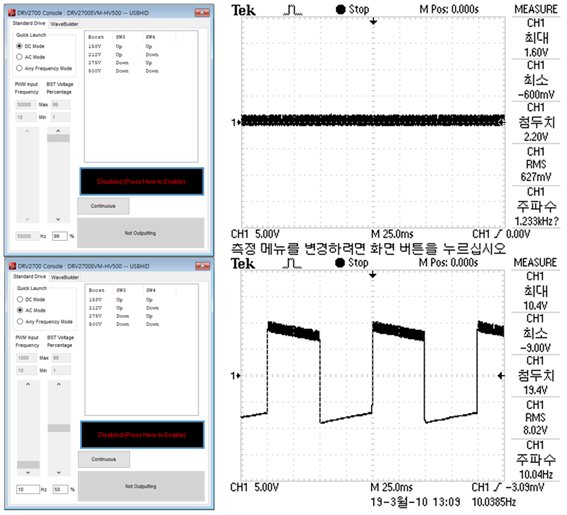
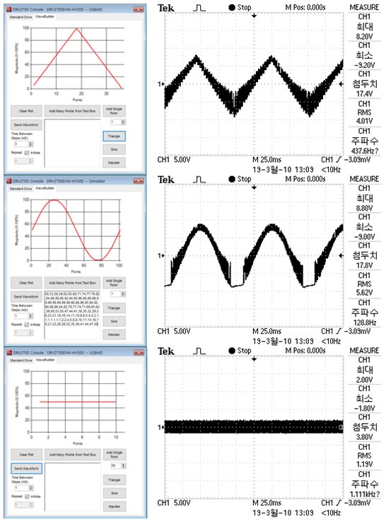
However, the noise is too severe to function properly.

(At the time of signal output, the setting screen of the programming tool and the shape and information of the output signal are attached to the file.)

Please check if the output information of the evaluation kit belongs to the normal category through the output signal of the attached file.

If this is a normal category, please advise how to solve the problem you are experiencing (serious noise).

- The environment using the evaluation kit is as follows.     

 : Operating system - window 7, window 10  

 : Power source - USB (2.0, 3.0 port)  

 : Setting voltage - 158 V (x 1/10 magnification at the time of measurement)  

 : Oscilloscope - Tektronix 'TDS1012B'

Ø Inquiry summary
- Goal: Various signal output using evaluation kit
       - Problem: Output of sine wave, square wave etc. is possible, but it does not function due to serious noise.
       - Content: Check whether the evaluation kit in use is working properly, how to attenuate noise during signal output


  • Hi Dae,

    What size load are you using on the output? Also how clean is the input signal?

    There will be some noise due to the hysteretic boost architecture, but it shouldn't be as bad as the attached images.
  • Hi Kelly,

    The voltage used on the attached figure is 158 V, and the voltage I will use 275 V or 500 V.

    The input signal was given through the computer usb port. However, I tried various notebooks and desktops, but the results were the same.

    How can I measure the hysteretic boost architecture? or is there a way to dampen noise by replacing parts?

    Regards,
    Daeyoung Lee
  • Hi Daeyoung,

    I understand the voltage you are using, but what is the load? Are you driving a capacitor? What is the capacitance?

  • Hi Kelly,

    I didn't understand exactly.
    What you are asking is what will i drive with the evaluation kit?

    i will drive a chip on a MEMS process.
    There are ITO patterns and SiO2 and so on..

    I want a clean signal.

    Is that what I understand well?

    Regards,
    Daeyoung Lee
  • Hi Daeyoung,

    The DRV2700 is designed to drive capacitive loads. Please try connecting a capacitor across the output and see if the output signal is less noisy.
  • Hi Kelly,

    As you said, I added a capacitor to the circuit and observed the signal.

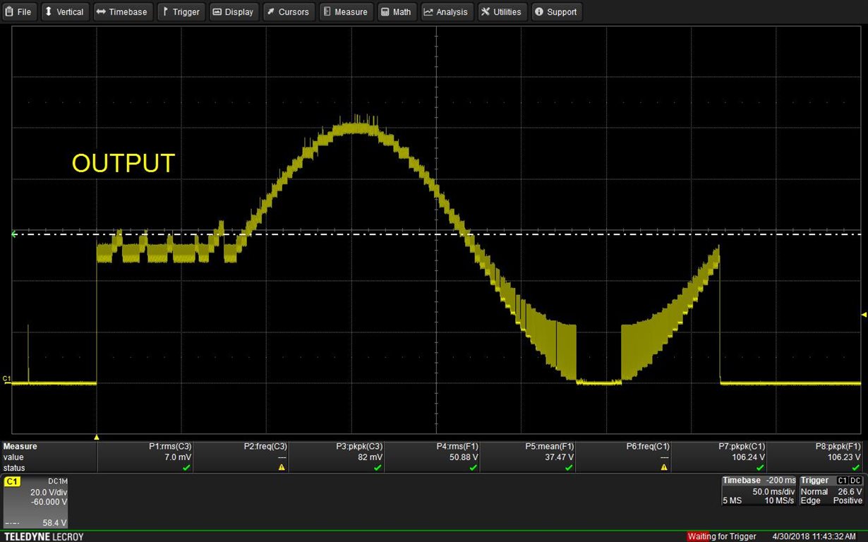
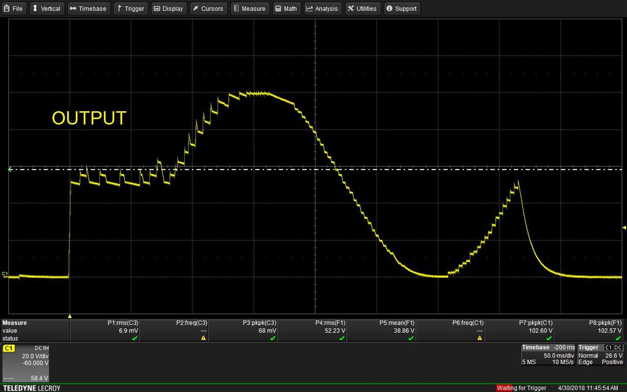
    There was no change in any capacitor(10 nF ~ 1 microF), and when the other capacitor(1000pF) voltage width was reduced.

    There is always noise.

    <with capacitor of 1000 pF>                                                     <with capacitor of 10 nF>

    thank you.

    Daeyoung Lee.

  • Hi Daeyoung,

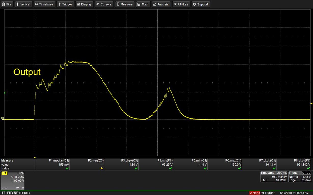
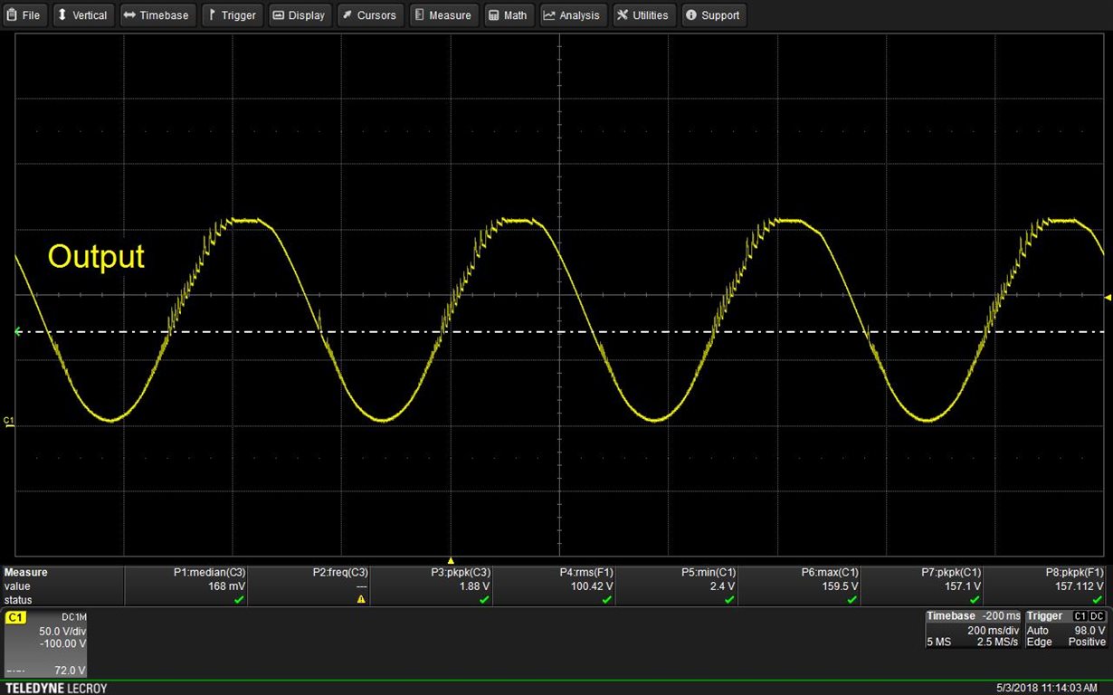
    If you look at the note in section 9.2.5 of the datasheet, it states higher load capacitance will reduce the ripple. In order to reduce noise in this type of design, you need to optimize the flyback circuit for the specific output voltage and load capacitance. I ran some tests and got the below waveforms.. Even these waveforms are a little off. I am getting a new EVM to perform some additional tests.

    Also I noticed that your output is going negative. Is your scope AC coupled?

    10nF load

    880nF load

  • Hi Daeyoung,

    I tested again with a new EVM and I am able to reach the 158V output. The previous EVM must have been damaged. The results are similar. Add additional capacitance to reduce noise. However, there is still some significant noise in the sine wave. I suggest fine tuning the flyback configuration for your specific voltage needed and making a new board. We walk through a lot of the design information in the DRV2700 datasheet and DRV2700EVM-HV500 user guide.

    10nF load

    880nF load

    880nF load with analog input

  • Please let us know if you have any additional questions. I will go ahead and close this E2E message thread for now.
  • Hi Kelly,

    Thank you for your efforts.

    I am sorry to leave the message late.

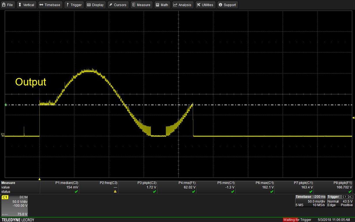
    with 47 nF capacitor, setting voltage: 275 V, frequency: 10 Hz


    However, the signal has improved a lot, but the signal from the function generator has a different effect.

    Thank you,

    Daeyoung Lee.

  • Thank you for following up. I'm glad the output is looking better for you now.
  • Hi Kelly,

    The noise content has improved a lot because of you.

    The signal of this product is offset and output as shown in the picture.

    I want a normal sine wave, not an offset signal as shown in the picture.

    Let me know if you have a way.

    Thank you.

    Daeyoung Lee

  • Hi Daeyoung,

    Sorry, there is not a way to do this with a single driver. In order to get the differential output, you could try using two devices and hook each output up to opposite terminals of your load. Then setup the inputs to drive half sine waves 180 degrees out of phase.
  • Hi Kelly,

    Does that mean to combine the sine waveform of the current kit with the dc waveform of another kit to eliminate the offset?
    Is it possible to output the dc voltage in the opposite direction?

    I don't know if I understand it properly.

    Thank you,
    Daeyoung Lee
  • Hi Daeyoung,

    You will not be outputting voltage in the negative direction. If you connect your load differentially, then you can apply +500V to the positive terminal and +500V to the negative terminal. The load will see 1000V AC signal based around GND.
    If you are driving a single ended load with the other terminal connected o GND, then this is not possible.