A related question is a question created from another question. When the related question is created, it will be automatically linked to the original question.
If you have a related question, please click the "Ask a related question" button in the top right corner. The newly created question will be automatically linked to this question.
A customer asked me about the results of the short-circuit test. Waveforms and questions are included in the attached document, so could you please comment?
Please see section 7.3.8.3 of the datasheet. This explains there is an analog current limit on a short-circuit event that attempts to reduce the current before a OCP event occurs after Iocp deglitch. This is different from Itrip....I don't believe that Itrip is happening.
Also, is the fault LATCHED? If latched, customer would have to cycle nSLEEP or device power to recover. If it is latched, than can only be OCP or OTSD. Sometimes it is hard to determine in OTSD as temperature rises very quickly on the die itself and camera is not fast enough to pick up change or thermocouple is also not fast enough.
This block is quite common. You can check DRV8881 datasheet...same description is there. It is not new and entire DRV84xx family shares this operation.
1) Current limit starts when current is > Iocp. Current will continue to rise until Rdson increases as part of limiting the gate drive. It will then begin to fall.
2) There is no blanking time on this feature.
3) This is expected behavior. Device will protect itself as you see.
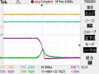
We got that Waveform1 which we attached is expected behavior.
However, we would like to confirm Waveform2.
There is the difference between Waveform1 and Waveform2 in spite of the same short conditions.
In case of Waveform2, compared with Waveform1, it seems that current falls rapidly.
Is it relation to following your comment?
“Current will continue to rise until Rdson increases as part of limiting the gate drive. It will then begin to fall. “
If it not have any relation of Rdson increasing, do you have any advice for it? For example : during Toff with the slow decay mode, it occurs short event, it might this problem,,,
Then, you mentioned followings;
“Also, is the fault LATCHED? If latched, customer would have to cycle nSLEEP or device power to recover. If it is latched, than can only be OCP or OTSD. Sometimes it is hard to determine in OTSD as temperature rises very quickly on the die itself and camera is not fast enough to pick up change or thermocouple is also not fast enough.”
->The customer checked the fault LATCHED. Therefore the fault can only be OCP or OTSD.
About OTSD, the customer checked the device with their hand, however there is no hot.
Especially, we would like to know why Waveform2 cause of.
In waveform 2, it appears that in CH3 (AOUT2), the low-side is switching on. In waveform 1, the output is staying high and high-current condition continues. I forgot to ask before, but this is an OUTPUT-to-OUTPUT short? I think so.
It is possible to hit Itrip before Iocp under some conditions. Especially if there is inductance in the short or the short is applied at the end of a long cable (with inductance). This will slow down the current rise just long enough to have Itrip before Iocp. They are seperate circuits as explained before. If Itrip happens, slow decay mode can occur and both outputs will go to LOW state. This will reduce the current more quickly.
I believe that is what is going on in waveform 2 case.
Can you tell me what the input state is when this short is applied...same for both waveforms?
1). Is the motor moving and short applied? Same condition for waveform #1/#2?
2) Is motor loaded?
3) What is the DECAY mode?
4) What is VREF?
5) Is the same behavior observed on B channel?
Is waveform #2 repeatable? Is short applied in waveform #2 soon after short applied in waveform #1? Or is there a long time between short conditions? How is the fault cleared between shorts? nSLEEP cycled or power cycled?
Not sure how to explain this without understanding input conditions and if the device is going into start of current regulation when short is applied. Device survives every short? If so, then what is the customer concern?
・Reason for asserting nFault ・Clamping in a short time is different from waveform # 1, but can it be considered to be due to the current limiting circuit of OCP?
If they wait a longer period of time between first short and consecutive shorts, do they still get a waveform similar to #2 or does every short look like #1? I would like to see if they could wait 30 seconds or even a minute between shorts . This would allow the device to cool between shorts and this would help me better understand if thermal protection is playing a role here.
Thank you! Seems not related to thermal. What are the state of the inputs during these shorting events? Are they transitioning at all or held at a steady state? If held at a steady state, what are the voltages on each input pin?
What are the state of the inputs during these shorting events? Are they transitioning at all or held at a steady state? If held at a steady state, what are the voltages on each input pin? ->We heard that they keeps the same input conditions, we will confirm it again. And then, we will reguest the customer get the waveform.
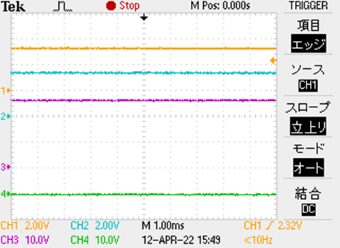
As the reference, the customer has gotten input condtions before short tests. (Please refer to the wave form.) CH1=AEN, CH2=APH, CH3=AOUT1, CH4=AOUT2
We attach the waveform which the customer captured inputs conditions during short test. (CH1=AEN, CH2=APH, CH3=AOUT1, CH4=AOUT2) It seems that inputs are not noisy, and these signals are steady state 3.3V.
I would check if differences in turning off behaviour are not caused by switch that performs short circuit. I would check voltage waveforms directly on both contacts of the switch, after short starts they both should stay the same. If the switch is of mechanical type then contacts bouncing may happen, though it usually lasts single milliseconds not microseconds.
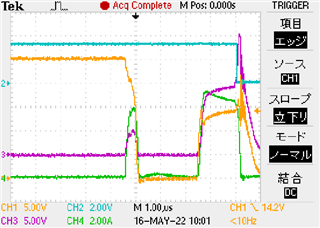
The waveforms posted so far have a test pin connected to the OUT terminal of the device on the customer's board, and a short-circuit test was performed by contacting the lead wire with this test pin. In addition, the waveform when the short-circuit test was performed using the mechanical switch is attached. I don't think there is any impact from chattering, but I would appreciate any comments.
Ch1: AOUT1, Ch2:nFAULT, Ch3:AOUT3, Ch4:Short current
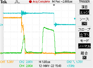
Ch1:Both ends of the mechanical switch, Ch2:nFAULT, Ch4:Short current
I really have no explanation for this. CH1 looks like it is being pulled to GND (or near GND) and then spontaneously recovers after ~2.5us. Current rises back up and a fault occurs. I checked some previous plots and it seems that VM and VCP are stable. Is VCP measured differentially with respect to VM? If VCP collapses, that could explain why the high-side is collapsing.
I agree with you, chattering/ contacts bouncing probably does not cause the switching differences, after short is made AOUT1 and AOUT3 stays at the same level (the first of the last waveforms you sent) .
Looking at longer current waveforms we can see that they last around 1.6-2us what would suggest current is turned off by OCP circuit with OCP deglitch time 1.8us. At the time of current negative slope significant ringing occurs at AOUT terminals what would suggest current is turned off quickly during fast decay caused by turning all Mosfets off by OCP circuit.
Looking at shorter current waveforms we can see that most of them decay slowly at the beginning with no ringing, I think that part is caused by Itrip circuit with slow decay mode. After 1.5-2us current starts to decay faster causing ringing, that part can be caused by OCP circuit with fast asynchronous decay. I guess Itrip circuit can switch current off without additional delay (1us blanking time) if APH and AEN terminals have been ON long enough before short occurs. I can not explain time between short and long current waveforms that is around 2.5us instead of 7us minimum (PWM off-time).
Making short circuit tests with different TOFF time and DECAY settings might help to better understand switching off process and check if what I said may be true.
All above are just my thoughts, I do not have experience with DRV8426 and I may be wrong.
The customer measured the waveform under the following conditions. ① After shorting the output, the input signal (APH, AEN) is changed from Low to High. -Ripple control decay ② After setting the input signal to High, short the output. -Mixed decay -Toff = 7us ③ After setting the input signal to High, short the output. -Mixed decay -Toff = 32us Each test was performed 5 times in a row, and similar waveforms were obtained.
From these data, "If APH / AEN is not constantly changing in the H state, there is no blanking time for Itrip, so when it hits the Trip current, it is in operation to enter Decay control.” Is the recognition correct?
Thank you! Good clues, but I am confused by your statement underlined below. Can you please add more words to help me understand?
If APH / AEN is not constantly changing in the H state, there is no blanking time for Itrip, so when it hits the Trip current, it is in operation to enter Decay control
Sorry for the lack of explanation. We have created materials about the test conditions and the short test that was conducted. I would appreciate it if you could check the attached file and comment.
I believe that Grzegorz-san provided the missing piece to this puzzle!! A month ago, we both guessed it was Itrip (scroll up about 1 month ago) as it appeared the device was going into slow decay.
What I didn't think about was the blanking time with static inputs. That is the piece that Grzegorz-san provided and the debug to get there was a good suggestion.
I think your presentation is perfect. Please close this case with the customer.