HI all,
I'm trying to realize a simple 2 x audio splitter using TLE2426 IC to have a dual power supply froma a single one.
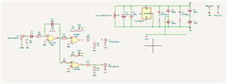
Am I on the right way?
Thank all for support,
Leonard
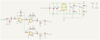
HI all,
I'm trying to realize a simple 2 x audio splitter using TLE2426 IC to have a dual power supply froma a single one.
Am I on the right way?
Thank all for support,
Leonard