Hi team,
The sensor is powered by 24-V DC and the probe outputs an AC signal from 2 Hz to 5000 Hz.(The sensor is similar to mic, and it has two wires, Signal and GND, where the signal pin is both the supply V+ pin and the output voltage signal)
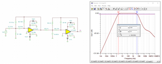
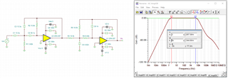
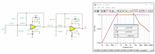
The customer wants to design a filter circuit to filter out spurious signals above 5000 Hz while ensuring less than 5% attenuation in signal voltage between 2 and 5000, and also the 24-V DC signal needs to be isolated. However, if the DC is isolated directly by a capacitor, there is a situation where the low-frequency (including 2 Hz) signal is attenuated.
Could you help tell how to design a circuit that can safely pass the 2-5000Hz signal, attenuate over 5K signals, and filter out the DC 24V? Thanks.
Best Regards,
Cherry