This thread has been locked.

If you have a related question, please click the "Ask a related question" button in the top right corner. The newly created question will be automatically linked to this question.

LMK03200: LMK03200 direct VCO output has interference

Part Number: LMK03200


  I need the LMK03200's VCO to output a 1.25Ghz sinusoidal signal. After configuring the registers and outputting a locked 1.25Ghz sinusoidal signal, as shown in Figure 1 and Figure 2 when viewed through the spectrometer, I find that it is 700M and 300M except 1.25Ghz All have very high energy, which has a great impact on my next design.

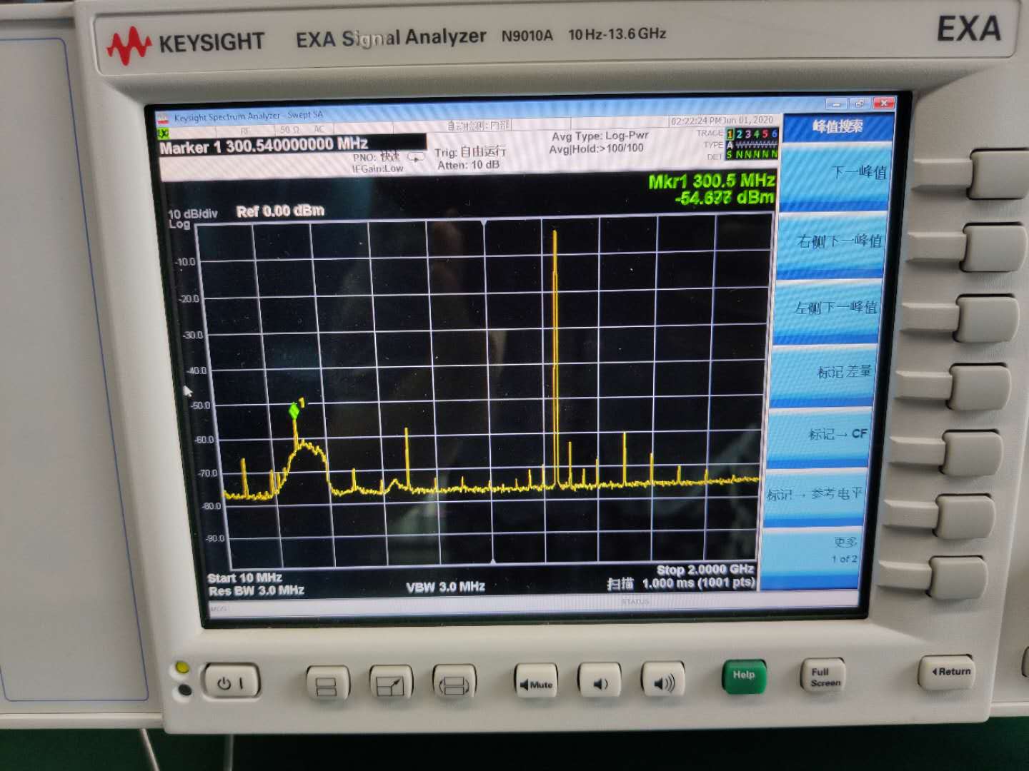
Figure 1 300Mhz has a very wide energy output

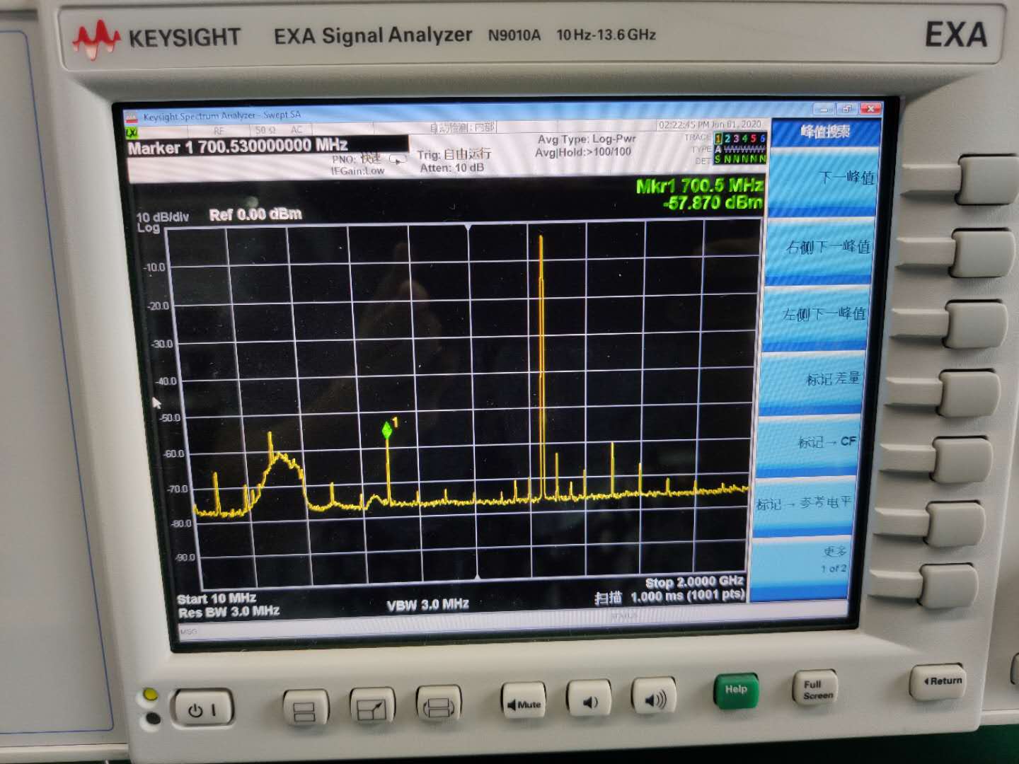
Figure 2 700Mhz also appeared interference energy

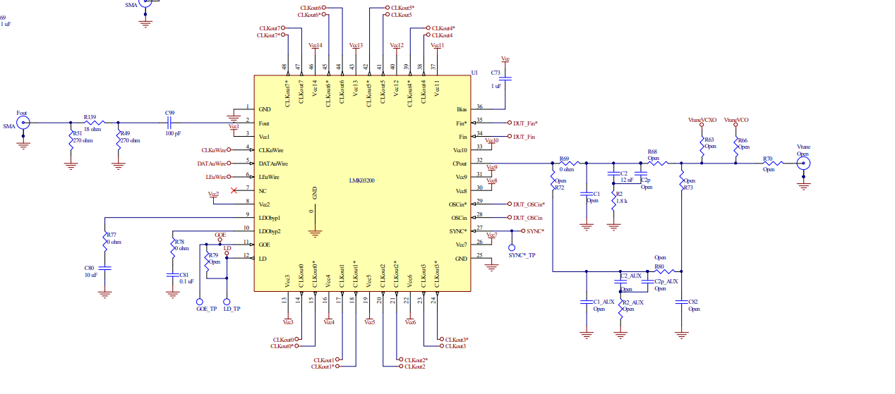
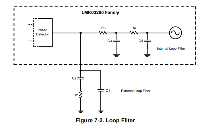
  The Fout filter circuit is exactly the same as the Fout filter circuit in the manual. The filter parameters are modified according to the calculation values of the Clock Design Tool software provided by TI's official website according to my needs.

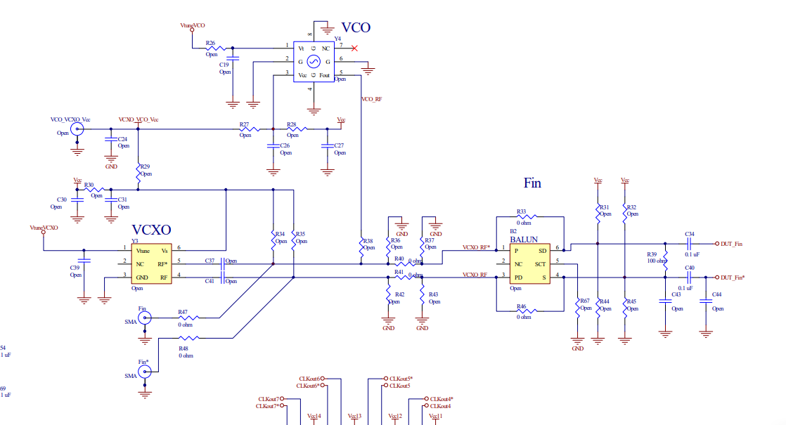
   According to the data sheet, the VPP output from the VCO should be around 1V, but the actual measurement is only 400mV. What do I need to do if I need a 1V Vpp?

  • Can you send the register dump and frequency plan? It appears the 300MHz and 700MHz spurs are due to mixing of frequencies in the system.

    From this row in the datasheet, convert 3.3dBm to Watts: (10^(3.3/10))/1000 = 2.1mW
    from P = V^2/R : V = 327mVrms, or 462mVpp, close to your measurement.

    For 1Vpp: R = 234ohm by the same calculation above, if that is an acceptable solution for you.

    Kind regards,
    Lane

  •  Dear Lane!

    Thank you for your answer.My input clock is a 100Mhz square wave signal, I want to get a 1.25Ghz sinusoidal signal through the VCO output of LMK03200.Since I only need the VCO output, I turned off all OUT_CLK.

    This flowchart is my register configuration process.

    figure 1 LMK03200 configuration process


    Kind regards,
    Queen

  • Hi Queen,

    Thanks, your registers look OK. We could expect spurs at 300MHz and 700MHz as they are harmonics of the input frequency, but it is not clear why they have so much energy. If the spurs are not generated from the clock source, or some other interfering signal, it may be required to find a creative work around.

    Kind regards,
    Lane 

  •   In order to eliminate the influence of the harmonics of the external clock, cut off the external clock source and observe the energy distribution on the spectrum analyzer again. It is found that the energy of 700Mhz has disappeared, but the part of 300Mhz still exists. As shown in the red circle on the spectrum analyzer in Figure 1.

    Figure 1 LMK03200 has no clock input

  • Thanks for the update. The spectrum plot is the same as before; I wouldn't expect activity at 300MHz if the input is turned off. Is it generated from elsewhere in the system?

    Are you testing on LMK03200EVAL, or another board?

    Kind regards,
    Lane

  •   thank you for your reply. In order to accurately locate the problem, I am applying for the LMK03200 EVAL board as a performance comparison test. But it has been a long time and I have not received a reply.

  • Thanks for the update. I will await your next update once you receive the EVAL board

    Kind regards,
    Lane

  •   Dear Lane, because the application time for the EVAL board is too long, can you please use EVAL to help test the VCO output spectrum of the LMK03200?

  • I will try to capture the measurement, but I need to locate a board first, I will provide an update by next week.

    Kind regards,
    Lane

  • Dear Lane

    do you have any results here?

  • Hi Queen,

    I was able to locate a board but several modifications were made to it. I am reworking and testing the board now. If all goes well with this board I should have some results next week.

    Kind regards,
    Lane

  • Dear Lane

    Thank you for your help, I look forward to your reply.

  • Hi Queen,

    Here is a plot of the output spectrum. Attached the device configuration from TICS Pro as well. My noise measurement floor was not as low as yours, but i Didn't observe any large spurs above -60dBc. Next time I go to the lab, I can increase the resolution bandwidth to get a lower noise floor just to get the noise floor closer to your measurement.LMK032000 Fout 1250MHz.tcs

    Kind regards,
    Lane

  • Dear Lane,

            Please help to confirm whether the DEMO you are using is the LMK03200EVAL model board, and whether the circuit part is completely consistent with this schematic diagram. If it is different, please help to point out different BOM materials so that we can modify the circuit to match yours. DEMO is consistent, thank you~

  • Hi Queen,

    Here is the measurement with increased resolution bandwidth. I'm only seeing one tone at 320MHz, this is likely an interference from nearby equipment in my lab.

    The following changes were made to the board in order to use a differential OSCin input. Also, the loop filter is changed, but I'm not sure exactly which values are on the board.

    Kind regards,
    Lane

  • Dear Lane,

    As you can see from the latest test chart, both scenes have 320Mhz of energy. Can you rule out that this part must not be generated by LMK03200, because the test scenes on our two sides should never be the same, my side It also happens that the possibility of interference of 320Mhz is relatively low. Whether the LMK03200 is very easy to be interfered at the frequency of 320Mhz. Is there a way to suppress this problem? I look forward to your further answer~

  • Hi Queen,

    I'm not sure how to suppress this spur. Typically spurs can be improved by improving the frequency plan but changing the reference frequency didn't appear to have a big impact

    Kind regards,
    Lane

  • Dear Lane,

      thank you for your help.