Tim Green
Here is the moment you have all been waiting for – the answers to the six op amp puzzles I posted last week. You know, the ones that you have all been puzzling and puzzling until your puzzler is sore! Score your number of right answers and bestow upon yourself the appropriate ranking at the end of this blog!
Repeated for reference are some key op amp specifications in Figure 1. By the way, the specifications given in Figure 1 are, like college and the real world, not all needed to solve the puzzles!
|
PARAMETER |
|
CONDITION |
UNIT |
|||
|
|
MIN |
TYP |
MAX |
|||
|
|
|
Vs=±5V unless otherwise noted |
|
|
|
|
|
Operating Voltage Range |
VS |
|
±1.35 |
|
±6 |
V |
|
Common-Mode Voltage Range |
VCM |
|
(V-) -0.1 |
|
(V+) - 1.5 |
V |
|
Short Circuit Current |
ISC |
|
|
±23.5 |
|
mA |
|
Voltage Output Swing from Rail |
VO |
IOUT=+5ma (source) |
|
4.70 |
|
V |
|
|
VO |
IOUT= +10ma (source) |
|
4.44 |
|
V |
|
|
VO |
IOUT= +20ma (source) |
|
3.85 |
|
V |
|
|
VO |
IOUT= -5ma (sink) |
|
-4.81 |
|
V |
|
|
VO |
IOUT= -10ma (sink) |
|
-4.62 |
|
V |
|
|
VO |
IOUT= -20ma (sink) |
|
-4.00 |
|
V |
|
Input Offset Voltage |
VOS |
|
|
1 |
5 |
uV |
|
Input Bias Current |
IB |
VCM=VS/2 |
|
±100 |
±200 |
pA |
|
Input Offset Current |
IB |
VCM=VS/2 |
|
±200 |
±300 |
pA |
Figure 1: Key Op Amp Specification for OPA735
Puzzle #1: What is Vout?
Answer: Vin=1V, Vout=2.97V
I would accept Vout = 3V for the ideal first look. This topology is a V-I (Voltage-to-Current) converter. It yields Iout for Vin and is known as the Improved Howland Current Pump. For R5=R2 and R4=R3, the single-ended to differential gain from Vin to voltage across R1 is V_R1 = Vin *(R5/R4). Then Iout = V_R1/R1. In our case, then Iout = Vin/R1 or Iout = Vin/100. And so Vout = Iout * RLoad.
Puzzle #2: What is Vout?
Answer: Vin =1V, Vout= -4V
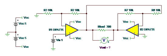
This is a BTL (Bridge-Tied-Load) circuit. Voltage gain across the load, Rload, is double that out of U1. This is because the output of U1 is inverted through U2.
For our given resistor values, gain of U1 is +2 and gain of U2 is -1, so we expect Vout_U1 = 2V and Vout_U2 = -1*Vout_U1 = -2V. Given the polarity of the meter, Vout, across Rload
Vout=-4V.
This is a great circuit to get positive and negative voltage across a floating load on a single supply. It will also give you double the slew rate and double the voltage across the load.
Puzzle #3: What is Vout?
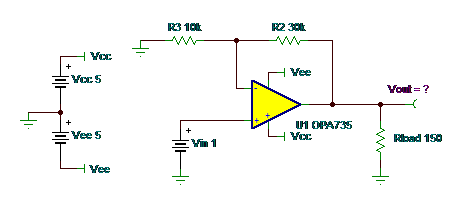
Answer: 23.5mA X 150 ohms = 3.52V = Vout
Closed loop gain on this is x4. Vin of 1 means you should get 4V at Vout. Iout = 4V/150 ohms =26.67mA. But from our specifications in Figure 1, there is a current limit of +/-23.5mA, so 23.5mA X 150 ohms = 3.52V = Vout.
We are still trying to design the virtual op amp that has unlimited output current!
Puzzle #4: What is Vout?
Answer: Anything less than Vout=4V–100mV
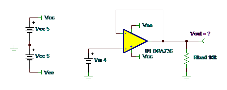
This is a unity gain buffer amplifier circuit, so closed loop gain is 1. So why isn’t Vout = 4V?
Look at Figure 1 and the common-mode voltage range, which is (V+) -1.5V. So for a Vcc = +5V my input-positive common-mode voltage range is only up to +3.5V. You should especially be aware of the input common-mode voltage range in unity gain buffer circuits
The real IC may not clamp at the input common mode voltage range, as the simulation macromodel did. The real part will not be as accurate in this common mode violation as it would be if you were within the common mode voltage range. So, I will take a right answer as anything less than 4V–100mV!!
Puzzle #5: What is Vout?
Answer: Indeterminate
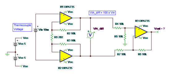
Why isn’t Vout = 10mV *100 = 1V? What in the heck is going on? The front-end instrumentation amplifier, U1 and U2, has a differential gain of 100. And the output difference amplifier, U3, rejects common mode and only amplifies the differential voltage out of U1 and U2 by 1.
Well, my esteemed readers, the input thermocouple, modeled as a battery connected differentially across Vin, is floating with respect to the ground reference for the power supplies that power the input op amps, U1 and U2. This means there is no DC bias current path for the +inputs of U1 and U2. Therefore, these op amp inputs are floating.
If you build this and test it, you may find any number of Vout voltages. Most likely a saturated U3 output near Vcc or Vee. So I will take for the right answer something like – indeterminate or any answer other than 1V!
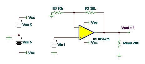
Puzzle #6: What is Vout?
Answer: Vout=3.85V
Closed loop gain on this is x4. Vin of 1 means one should get 4V at Vout. But from our specifications in Figure 1, there is a voltage output swing from rail specification of Vout=3.85V at Iout=20mA.
In this circuit, current limit is not the limiting factor, but swing to rail versus output current is. So you need to check the “Output Voltage Swing to Rail vs Output Current” data sheet curve for your large signal swing limitations at higher currents.
I added the specifications from the data sheet graph into Figure 1 so you wouldn’t need to look further to solve Puzzle #6.
Ranking:
|
Correct answers |
Bestow-able title |
|
1 |
Software engineer or PHD |
|
2 |
Digital engineer or firmware engineer |
|
3 |
Electrical engineering college intern or MSEE |
|
4 |
BSEE recent graduate |
|
5 |
Real-world analog board/system design engineer |
|
6 |
Honorary Texas Instruments analog applications engineer |
Thanks for taking a break from your “real work” to puzzle a bit on these op amp puzzles. Perhaps next year you can participate and postulate again whilst I perpetuate the op amp puzzlement to a proper portrayal of preventative procedures when using op amps.
I’m Vout-ta here for now!
PS: If you missed last week’s blog and thought this was fun, you might want to check out these posts from long-time TIer and retiree Bruce Trump.
- Resistor Puzzle—the sequel
- Resistor Puzzle Solution... and a rant on schematics
- Holiday Brain Teaser
- Brain Teaser—the solution
- Resistor Noise—reviewing basics, plus a Fun Quiz
- Temperature Effects on Input Bias Current… plus a Random Quiz


