

Calculating resistor self-heating. It’s a fairly fundamental concept that is often unfamiliar to, or overlooked by, many engineers.
I was reminded of its importance while explaining the theory behind a precision resistance temperature detector (RTD) acquisition system I recently designed. The design is featured in TI Designs – Precision reference design TIPD152. In the design, simplified in Figure 1, the errors due to the self-heating of the resistors in the signal path need to be considered to prevent them from causing undesired error levels.

Figure 1: Simplified Ratiometric RTD System
The design is configured for a ratiometric measurement, so the final analog-to-digital converter (ADC) conversion result is directly dependant on the absolute value of a reference resistor, RREF. Because an excitation current flows through RREF, it will dissipate power and therefore self-heat, causing a change in resistance affecting the system accuracy. The effects of resistor self-heating are also important in many other applications, such as current sensing or power-metering, that depend on the absolute value of a resistor that may change in value as it dissipates power.
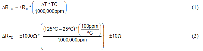
The temperature coefficient, or TC, of a resistor specifies how much the resistance will change when the resistor temperature changes. Resistor TC is typically specified in parts per million per degree Celsius, ppm/°C. A 1% resistor typically has a TC around +/-100ppm/°C, while precision metal foil resistors offer TCs less than 0. 1ppm/°C.
Equations 1 and 2 show an example of how you can use a resistor’s TC specification to calculate the change in resistance, ΔRTC of a 1kΩ, ±100ppm/°C resistor when the temperature changes from 25°C to 125°C.
In general, smaller surface mount components (0201, 0402, 0603, etc.) are less effective at dissipating power resulting in very high self-heating coefficients, θSH, up to, and sometimes over 1000°C/W! Granted these smaller resistors are usually rated for power levels <0.1W, but their temperature will change very quickly with dissipated power.
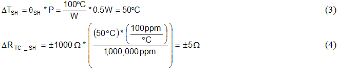
Equation 3 calculates the increase in resistor temperature, ΔTSH, due to the power dissipation. Equation 4 plugs ΔTSH into Equation 1 in place of ΔT to determine the resistance change due to self-heating with a modest self-heating of 100°C/W and 0.5W of power dissipation.
Although you won’t usually find the self-heating coefficient in a resistor datasheet, you can back-calculate it from the power derating curve, which is typically included.
The power derating curve dictates the maximum power dissipation versus ambient temperature that the resistor can dissipate without exceeding the maximum specified temperature. Figure 1 shows an example of a resistor power derating curve for a 0.5W resistor.
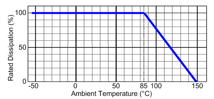
Figure 2: Example Power Derating Curve for 0.5W Resistor
You can easily determine the maximum operating temperature, TMAX, from the curve in Figure 1 as the value on the x-axis when the rated dissipation = 0%. In the example shown, the maximum operating temperature is 150°C.
Further, the resistor can no longer operate at 100% of the rated dissipation, TMAX_PWR100%, at 85°C. Using this temperature, the maximum operating temperature and the power rating of the resistor, you can calculate the value for θSH as shown in Equation 5.

With the coefficient of self-heating calculated, you can now determine the increase in heat, and therefore change in resistance, due to the power it is dissipating using Equations 3 and 4. From there, you can determine the effects on the final system accuracy based on the change in resistance.
So, next time you’re designing a system that requires precision resistor values, be sure to take resistor self-heating into account!
-

Sarang Suryawanshi96
-
Cancel
-
Vote Up
0
Vote Down
-
-
Sign in to reply
-
More
-
Cancel
Comment-

Sarang Suryawanshi96
-
Cancel
-
Vote Up
0
Vote Down
-
-
Sign in to reply
-
More
-
Cancel
Children