In my previous post, I explained how to design 2-wire, or loop-powered, analog outputs for industrial automation. In this post, with the design and operation of the transmitter in mind, I will talk about how to design circuits to protect these systems. For reference, Figure 1 shows the basic 2-wire transmitter design.
Figure 1: Basic 2-wire transmitter design
A protection circuit for a 2-wire transmitter needs to protect the system against two hazards:
- Industrial transients and radiated emissions.
- Reverse-polarity connection of the transmitter terminals.
The IEC61000-4 test standard replicates several common industrial transient signals and radiated emission conditions that my colleague, Ian Williams, has explained in a series you can read here. In short, these tests are high-voltage and sometimes high-current, fast-moving transients that can easily damage sensitive analog components. To protect the 2-wire transmitter from these signals, the voltage and current applied to the supply and/or return terminals must be limited.
Bidirectional transient-voltage-suppression (TVS) diodes are perfectly suited to limit the voltage across the terminals. These diodes are simple clamping devices that conduct when the voltage applied across their terminals exceeds their breakdown voltage. TVS diodes are manufactured with a variety of breakdown voltage options, and the breakdown voltage should be selected based on the maximum voltage that the regulator can accept in the 2-wire transmitter design. Low reverse-leakage current is also important to consider, as leakage can degrade the accuracy of the transmitter.
Including the TVS diode between the two transmitter terminals limits the voltage applied across the transmitter, but another component is required for the scheme to limit the current flowing through the transmitter. Series resistors are an option to limit current flowing through the transmitter, but the voltage drop across these resistors contributes to increased compliance voltage for the transmitter design, which is often not desirable. Ferrite beads, alternatively, are low impedance at DC and will not increase the compliance voltage of the design, but still provide a method to limit series current for fast-moving transients. Figure 2 shows the complete design up to this point, including an optional capacitor to help further attenuate fast-moving transients.
Figure 2: Basic 2-wire transmitter design with transient protection
The transmitter also needs to be protected against reverse-polarity connections of the supply and return terminal, since terminal misconnection is possible. One option is to place series diodes on the supply and return paths to prevent current from flowing in the reverse direction. In this case, the transmitter is not damaged from the reverse current flow, but the transmitter is nonfunctional until the connections are applied correctly.
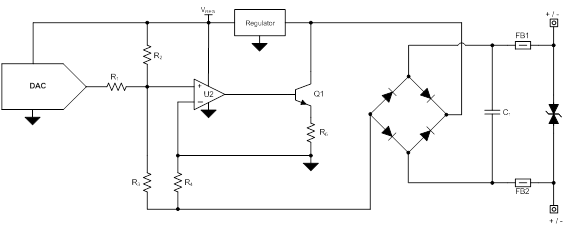
An alternative reverse-polarity protection solution is to place four diodes in a bridge configuration, as shown in the complete solution shown in Figure 3, in-between the transmitter and the TVS diode/ferrite beads. In this configuration, the diode bridge rectifies the supply and return connections for the transmitter to function properly, regardless of which terminal is connected to supply and return.
Figure 3: Basic 2-wire transmitter design with complete protection
This post concludes the Industrial DAC series, which should leave you prepared with the fundamentals of design and protection for industrial analog output modules. If there’s anything you’d like to hear more about in a future post, leave a message in the comments below.
Additional resources:
You can see the protection schemes discussed in this post in practice in TI’s TIPD158 loop powered transmitter and TIPD126 bridge sensor signal conditioner with current loop output.
Read more posts in the Industrial DACs series.
Learn about TI’s data converter portfolio and find technical resources.
Explore our portfolio of precision DACs and find related technical resources for your design.


