

In part 1 of this series, I explained how you can calculate the input voltage to an analog-to-digital converter (ADC) by multiplying the ADC’s output code by the least-significant bit (LSB) size using Equation 1:

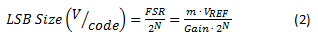
To calculate the ADC’s LSB size, we used Equation 2:
Now that you know how to calculate the input voltage from the output code, let’s look at a few common application examples that use delta-sigma ADCs to show how to calculate the physical parameter of interest from the measured voltage. With each example, I’ve provided links to a related TI Designs reference design where you can go to get additional design help.
Current-shunt measurements
ADCs measure voltage; therefore, you must first convert the current into a voltage. The easiest way to do this is to force the current through a resistor with a known value, as shown in Figure 1.

Figure 1: Current-shunt measurement
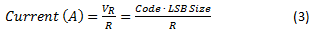
The relationship between current and voltage is given by Ohm’s law (V = I ∙ R). To retrieve the current amplitude, I, take the voltage measured by the ADC across the resistor, VR, and divide it by the resistance, R, as shown by Equation 3:
Ensuring the accuracy of the current measurement requires a precise and stable shunt resistor. Additional design considerations can be found in the TI Designs Voltage and Current Measurement Reference Design for Automotive On-Board Charger System (TIDA-00456).
RTD temperature measurements
A resistance temperature detector (RTD) is a temperature sensor with a temperature-dependent resistance. The ADC indirectly measures the RTD resistance and infers the RTD temperature. The measurement configuration is similar to Figure 1, except that a known excitation current, IExcite, is forced through the resistor to produce a voltage. This current can also generate the ADC’s reference voltage to make the measurement ratiometric, as shown in Figure 2.
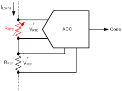
Figure 2: Ratiometric RTD measurement
To calculate the RTD resistance, RRTD, divide the measured voltage, VRTD, by the excitation current, IExcite, as shown by Equation 4:

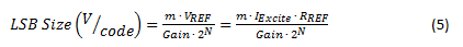
The accuracy of the current source would normally affect the accuracy of the resistance measurement; however, by using the ratiometric configuration shown in Figure 2, you can eliminate this dependency. Notice how LSB size is proportional to the excitation current, as shown by Equation 5:
Substituting Equation 5 into Equation 4 results in a ratiometric relationship that does not depend on the amplitude of the excitation current, as shown by Equation 6:

Now the accuracy of the measurement depends mainly on the stability of the reference resistor, which is generally much better than the stability of the excitation current. This configuration is called ratiometric because the ADC’s output code is proportional to the ratio of the RTD and reference resistors.
With the RTD resistance known, you must still determine the temperature of the RTD. Equation 7 uses the Callendar-Van Dusen equation to specify the relationship between temperature and RTD resistance:

where T is the RTD temperature; A, B and C are standard polynomial coefficients given by the RTD type; and R0 is the nominal resistance of the RTD at 0°C. Note that for temperatures above 0°C, you can simplify Equation 7 to solve directly for temperature, as shown by Equation 8:

In cases using only a small temperature range, make a linear approximation to simplify the temperature calculation. Alternatively, you could have the software reference a look-up table to convert the RTD resistance to a temperature without having to solve the polynomial equation.
An example of using a look-up table for RTD measurements can be found in TI Designs RTD Temperature Transmitter for 2-Wire, 4 to 20-mA Current Loop Systems reference design (TIDA-00095).
Thermocouple temperature measurements
A thermocouple is a temperature sensor that produces a temperature-dependent voltage output proportional to the temperature difference between two junctions: a sense/hot junction and a reference/cold junction. The ADC measures this voltage and converts it to a relative temperature (the temperature difference), as shown in Figure 3.
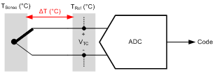
Figure 3: Thermocouple measurement
To determine the absolute temperature at the sense junction, TSense, add the relative temperature,  , to the reference junction temperature, TRef, which must be known either by controlling its temperature or measuring the temperature by some other method. Once the ADC has measured the input voltage, calculate the absolute temperature of the thermocouple using a polynomial equation, as shown in Equation 9:

Coefficients c0, c1, c2, …, cN are standard polynomial coefficients specific to the type of thermocouple and the temperature range of interest. In many cases, it is more convenient to use a look-up table instead of solving Equation 9, which may have a very high order.
An example of using a look-up table for thermocouple measurements can be found the TI Designs Thermocouple AFE Using RTD or Integrated Temperature Sensor for Cold Junction Compensation (CJC) reference design (TIDA-00168).
Load-cell measurements
Load cells consist of a combination of resistors in a bridge configuration, in which some of the elements (strain gauges) vary in resistance based on an applied load (or weight), as shown in Figure 4.
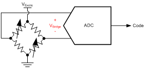
Figure 4: Load-cell measurement
The resistor bridge provides an output voltage that is proportional to the excitation voltage and applied load. Even though an applied load changes the resistance of the strain gauge, the resistance doesn’t need to be measured because of a very linear relationship between the applied load and output voltage, as shown by Equation 10:

where Applied Load (kg) is the weight placed on the load cell; Load Capacity (kg) is the rated weight capacity of the load cell; VExcite (V) is the excitation voltage applied to the load cell; and Sensitivity (mV/V) (the rated output) is a specified parameter given by the load-cell manufacturer, which indicates the output voltage of the load cell under full capacity with a 1V excitation voltage.
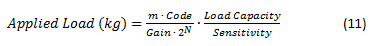
Note that changes in excitation voltage have a direct effect on the measurement result; therefore, it is common to use the excitation voltage as the reference voltage to make the measurement ratiometric and independent of the excitation voltage. When the reference voltage is equal to the excitation voltage, calculate the weight using Equation 11:
Other design considerations and a trick for improving weigh-scale accuracy can be found the TI Designs High-Resolution, Low-Drift, Precision Weigh-Scale Reference Design with AC Bridge Excitation (TIPD188).
These are just a handful of examples showing the basics of how to perform the conversion from ADC codes to the physical parameter of interest. Let me know in the comments if this overview was helpful, or if there’s a particular application I didn’t cover that you would like help decoding. Also, check out the Data Converter Learning Center for more ADC resources and let me know if there is another topic you would like me to discuss in a future Precision Hub blog post.
Additional resources
- Check out the ADS1118 BoosterPack, with example code for measuring K-type thermocouples
- Read more delta-sigma ADC blog posts.
- Search for solutions, get help and solve problems in the TI E2E™ Precision Data Converter Forum.
