

Last week for Halloween, I handed out candy to kids in all sorts of costumes. Some occupations make great costumes: fireman, policeman, doctor, professional athlete, and of course astronaut. But I’ll admit that every year I’m a bit disappointed that no little electrical engineers come to the door.
Sure, some of you may say things like, “it’s dangerous to let a child walk around the neighborhood with a soldering iron” or “my child is too small to carry an oscilloscope!” But I don’t buy these excuses. I think the real reason that kids don’t dress up like electrical engineers for Halloween is that most people don’t know what an electrical engineer does!
To remedy this situation, I thought I could do a little “show and tell” about my job in this week’s Precision Hub blog post. I’m a particular type of electrical engineer called an “applications engineer”. Simply put, an applications engineer helps customers use Texas Instruments ICs to build their products. In my case, I work with TI’s precision amplifier products.
My job responsibilities come in two categories: reactive and proactive.
A “reactive” responsibility is when a customer comes to TI directly with a question, normally through the TI E2E™ Community. It can be anything from a misunderstanding of a specification (see Figure 1) to “why does my device explode when I apply power?” Thankfully the latter is rare, but I’m sure that at any given moment, somewhere in the world an IC is being installed backwards. Always remember to check the pin 1 indicator!
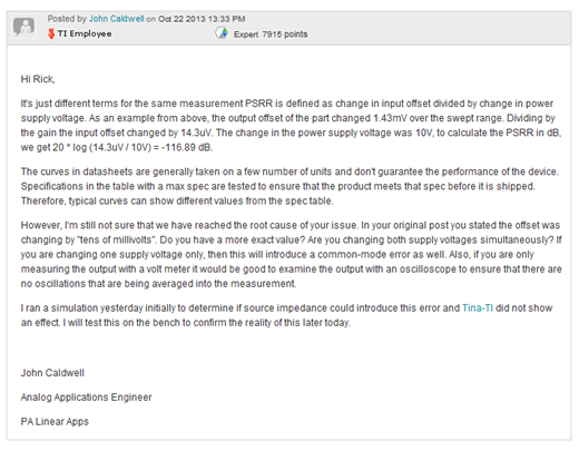
Figure 1
The reactive portion of my job has helped me to become an excellent debugger. Not only do I have to carefully examine circuit schematics, run simulations, and often duplicate systems in our labs, but I also have to imagine what’s NOT on the schematic.
For example, are the passive components causing the issue I came across in this thread? What environment is the PCB installed in? Has something happened to the system in the past that could have damaged it? If I find a particular question interesting, or many customers have asked it, I’ll try to write up the answer as a blog post – like this one I recently wrote about capacitor leakage current.
Occasionally, I even get to travel to our customers to work with them directly or give presentations on challenging aspects of precision analog design. This year I visited customers in The Netherlands. Last summer I lived in Germany so I could work with our customers there.
The proactive portion of my job involves thinking of new and creative things to build using TI ICs. We recently launched TI Precision Designs as a way to document the work of our applications team and allow others to use it. The inspiration for these reference designs can come from many different places: solving customer problems, exploiting unique aspects of a product, or even from personal projects.
For example, I wanted a low distortion PWM modulator for a Class-D audio amplifier I was building for my stereo at home. The circuit I came up with is detailed here. My actual test circuit schematic appears in Figure 2.
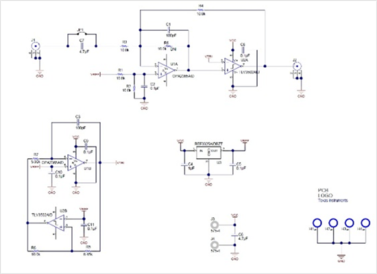
Figure 2
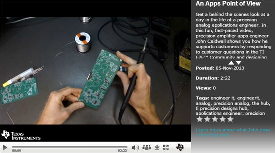
But enough of the “tell” portion of this blog. Earlier this year I took it upon myself to wear a camera on my head and document what a typical day is like. Click here or the screen shot below to launch video.
If you’re considering a career in electrical engineering, I recommend looking into applications engineering. It’s a rewarding job that constantly pushes me to be a better engineer. And if you’re thinking about what to be next year for Halloween, grab a lab coat and put on an ESD wrist strap! I guarantee you’ll get a lot more candy if you come to my door as an electrical engineer.

