

My esteemed colleague, John Caldwell (not to be confused with ‘John’ the intern), authored a couple excellent blogs about instrumentation amplifier (INA) power supply and common-mode rejection ratio (PSRR & CMRR). (See “Dealing with rejection: Instrumentation amplifier PSRR and CMRR,” Part I and Part II)
He correctly noted that the CMRR & PSRR performance of most INA devices changes with gain. But what about the handful of INAs whose CMRR does not change with gain?
Figure 1 shows the CMRR vs. Frequency datasheet plot for the low-power, single-supply INA331, which exhibits this behavior.

Figure 1: INA331 CMRR vs. Frequency
Although CMRR is measured according to Equation 1 below, Equation 2 depicts the academic definition of CMRR, where Adm is the differential gain and Acm is the common-mode gain.

Differential amplifiers, including INAs, attempt to reject common-mode signals and amplify the differential signal. Therefore, according to Equation 2, increasing Adm will increase CMRR. The 36-V, low-power, rail-to-rail output (RRO) INA826 depicts this behavior, as shown in Figure 2.
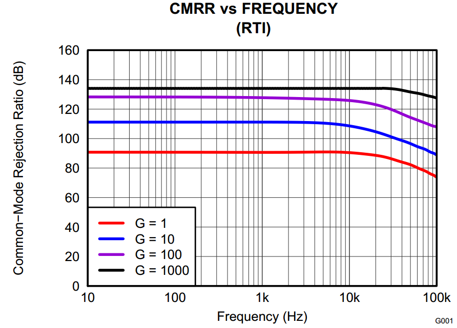
Figure 2: INA826 CMRR
So, why do the INA331 and INA826 behave differently when you change the device’s gain?
Figure 3 shows simplified schematics of the devices. They both have three op amps, differential inputs and single-ended outputs, and the gain is set using external resistor(s).

Figure 3: INA826 (left) vs. INA331 (right)
Even the gain equations, shown by Equations 3 and 4, look similar.

Examining the input and output stages of both devices will lead us to the answer.
Figure 4 shows the input (A1-A2) and output (A3) stages of the INA826. RG determines the overall gain of the device, because the gain of the output stage is fixed due to the integrated resistors. Since the input stage is differential, RG controls the differential gain of the device. Therefore, as the device’s gain changes, so does the CMRR performance.
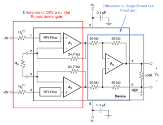
Figure 4: INA826 simplified schematic
Figure 5 shows the output stage (A3) of the INA331. R1 and R2 are external resistors that set the device’s gain according to Equation 4. Notice the output stage is single-ended.
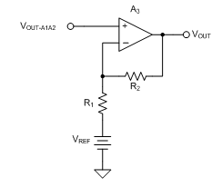
Figure 5: INA331 output stage, external resistors
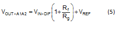
Figure 6 depicts a redrawn version of the INA331 input stage (A1-A2). Equation 5 is the transfer function for the circuit in Figure 6. The input stage of the INA331 performs three functions. It converts inputs from differential to single-ended signals, applies differential gain and adds the reference voltage.
All of the resistors in this stage are internal to the device. Therefore, the differential gain of the INA331 is fixed by the ratio of Rf to Rg!

Figure 6: INA331 input stage, all resistors internal
In summary, even though R1 and R2 change the gain of the INA331, they do not change the differential gain. The integrated resistors of the input stage fix the differential gain. This is why the CMRR of the device does not change with gain!
Other INAs that exhibit the same behavior are the single-supply, low-power, CMOS INA321, INA322 and INA332.
So, next time you’re changing the gain of an INA, be sure to understand which gain you’re changing…the CMRR depends on it!
-

Pete%20Semig
-
Cancel
-
Vote Up
0
Vote Down
-
-
Sign in to reply
-
More
-
Cancel
Comment-

Pete%20Semig
-
Cancel
-
Vote Up
0
Vote Down
-
-
Sign in to reply
-
More
-
Cancel
Children