This thread has been locked.

If you have a related question, please click the "Ask a related question" button in the top right corner. The newly created question will be automatically linked to this question.

THS3001: High Voltage, High Frequency Piezoelectric Drive

Part Number: THS3001
Other Parts Discussed in Thread: OPA2695, , THS3491, THS3217

Hello,


I am trying to design an amplifier for an ultrasound pulse/receive system with an output swing of at least 26 Vp-p, although something closer to 40 Vp-p would be nice, across a range of frequencies from 25 MHz to 75 MHz. The input signal is provided by a DAC/DDS and will likely be in the 100s of mV, therefore the overall amplifier gain must be around ~40 dB.

My intention is to use something like the OPA2695 as a pre-amplifier before the final output stage, however I've struggled to find an amplifier capable of providing any substantial gain at these frequencies when the output voltage swing is in the 10s of volts. After a lengthy parametric search, I believe the THS3001 may be capable of meeting my minimum requirements, however it is not entirely clear from the datasheet and I was hoping someone may be able to provide a bit of clarification.

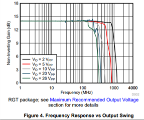
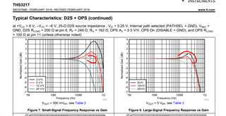
From the THS3001 datasheet, the electrical characteristics table states a typical voltage swing of either ±12.8 V or ±13.1 V for different values of RL. However, in the typical characteristics section, each of the Figures appear to have been recorded with inputs in the mV range and for very low gain, even those where the Vs span is 30 V. Is it possible to use this device with larger inputs signals and similar or greater levels of gain? And is this device capable of the stated ~25 V output span when operating at frequencies up to 75 MHz?


Thanks,
Lee

  • Hi Lee,

    a 40dB gain over a bandwidth of 75MHz means a gain-bandwidth product of

    100 x 75MHz = 7.9GHz

    without linearizing gain reserve and 79GHz for a gain reserve of 20dB. So you will need to evenly split the total gain over several amplifier stages.

    40Vpp means a slew rate of

    20V x 2 x pi x 75MHz = 9400V / µs

    and this only for a sine wave.

    Kai

  • Thanks for the reply, could you explain what you mean by "linearizing gain reserve"? I wasn't able to find anything after a quick Google.

    I am aware that this will be a multi-stage amplifier, however, my problem lies in that I cannot source an amplifier capable of an output voltage swing of at least 26 Vp-p with an operating frequency of 25 MHz to 75 MHz.

    The input/output signals will be sinusoidal.

  • Hi Lee,

    you usually have lots of gain reserve when using an amplifier. The gain reserve is the difference (when thinking in terms of dB) of open loop gain and loop gain at a certain frequency.

    Kai

  • Hi Lee,

    I will be taking a look at your design requirements and help you find a path forward on your design.

    Best,

    Alec

  • Hi Lee,

    THS3491 is probably a better bet for what you need than the THS3001. Figure 4 in its datasheet shows a frequency response curve with Vout=26Vpp with still over 200MHz of bandwidth. 

    The typical slew rate of 8000 V/us is pretty close to what you need. I haven't found an amplifier with a higher slew rate that can do that high voltage as fast.

    Thanks,

    Evan

  • Hi Lee,

    have you thought about using a bridged amplifier? This could double the slew rate.

    What is the load impedance of your piezoelectric device? I guess a lot of capacitance? This can result in huge load currents according to

    I = C x dU/dt

    Kai

  • Tough requirement - consider 

    1. THS3217 from DAC to single ended 10Vpp at gain of 10, 

    Then a THS3491 for the rest of the gain - if you are not volume production, you might just try the THS3491 at higher supplies - we validated operation up through about 48V in characterization, but did not specify as the process limits would not in theory support that. And then, with this kind of 9V/nsec slew rate, if your load is capacitive you will be asking for large transition currents - check that and stability. The THS3491 is the highest slew rate, highest output current,  op amp out there, so see what you can get out of that. Good thermal design will be mandatory, use the QFN with the heat spreading plate connecte to large plane, it has a die temp sense output also you will want to monitor. 

  • Thanks for this Evan, not sure how I missed the 3491 in my searching, but from a brief look at the datasheet it seems ideal! Will definitely be taking a further look.

  • I had briefly investigated bridge amplifiers, however I found it rather difficult to design such a circuit. I wasn't able to find any good, in-depth technical resources for learning more about this topology, but I would be very keen to read more if you have any recommendations :)

    As for the load impedance of the transducer, I'm unfortunately not sure. We manufacture our own transducers and have found them challenging to model, however I believe it is in the uF range.

  • Thanks for the reply Michael, the 3217 looks like it could be very useful for a lot of the work we do. This chip and the 3491 seem like a killer combo for this application :)

    The load will be capacitive, I believe in the uF range but I will hopefully have an approximate value soon - would you be able to expand on what you mean by checking the transition currents and stability? I'd also be keen to read more on this if you have any good material in mind. Same goes for thermal design - I don't have much experience with designing around loads which are this demanding, so any additional advice is much appreciated!

  • Hi Lee,

    loading a 1µF capacitance would mean a spike current of

    I = 1µF x 9400V/µs = 9400A

    Kai

  • Lee,

    I can take a look and see if there are any recommended resources for your design/application.  As mentioned above, the THS3491 is an incredibly capable part and would be a good choice for your design.

    Best,

    Alec

  • Hello Lee,

    I actually already have a good resource for you regarding operational amplifiers.  For things like stability, electrical overstress, bandwidth, etc, the TI video series TI Precision Labs: Op-Amps contains a wealth of information on these topics.  I encourage you to check it out and see if any topics cover your needs.  

    Here is the link to the video series homepage: training.ti.com/ti-precision-labs-op-amps

    And here is a link to an article a wrote about the video series: https://e2e.ti.com/blogs_/b/analogwire/posts/expand-your-engineering-knowledge-with-ti-precision-labs

    Best,

    Alec

  • Hello again Lee,

    For thermal design considerations, please consider the following two resources:

    Semiconductor and IC Package Thermal Metrics: https://www.ti.com/lit/an/spra953c/spra953c.pdf

    TI Precision Labs Videos w/ Thermal Content: https://training.ti.com/search-catalog/field_language/EN?keywords=thermal

    Best,

    Alec

  • Hi Alec,

    Thanks a lot for these, I have a lot of learning to do for this upcoming project so it is much appreciated :)