This thread has been locked.

If you have a related question, please click the "Ask a related question" button in the top right corner. The newly created question will be automatically linked to this question.

OPA657: High frequency current/power measurement (uA/uW level)

Part Number: OPA657
Other Parts Discussed in Thread: TINA-TI, LMH6629, OPA847

Hi , 

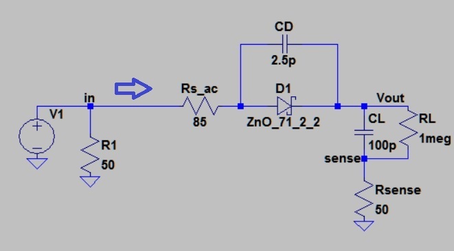
I am trying to measure the input power to my half wave rectifier (HWR) (shown below). R1(50 ohm) is just placed to match impedance and get the desired Vin and I don't care the power spent on it. What I am trying to do is measuring power consumed by the HWR. So I need to measure V_in and I_in without losing the phase information and multiply them in time domain, take average power on MATLAB. My Vin is (4Vp-p 100kHz to 10MHz, sine wave, testing one frequency at a time)

I placed Rsense (50ohm) just to measure the current and got the following V_sense and V_in from my simulations.


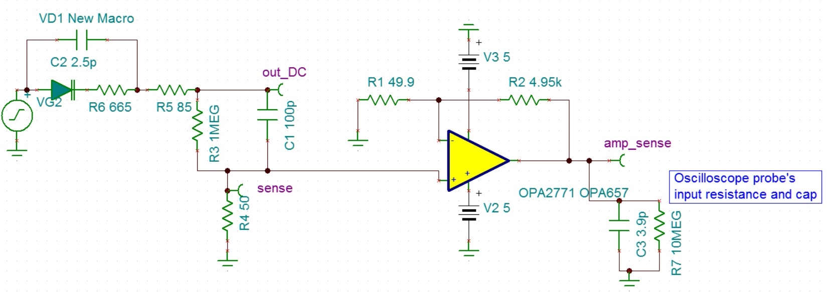
After searching for a high frequency, low input bias current opamp, I found OPA657 as a potential solution and designed the following amplifier.  

When I run the simulation on TINA-TI, it works ok at 1 MHz with 100 V/V gain but when I run it with 10 MHz at 100 V/V, I am getting a phase shift. If I reduce my gain to 10 V/V, it works ok even at 10 MHz but I don't want to reduce the input signal to the oscilloscope. 

My questions: 

- Would you recommend using an opamp other than OPA657? 

- Is there a better way to measure the input power ? I am open for suggestions. 

Thanks a lot, 

Levent

  • Hello Levent,
    Is the output of your OPA657 signal 4Vpp?

    At a gain of 100V/V your bandwidth is only 16 MHz which is why you are seeing the phase shift at 10 MHz. You will need a higher bandwidth amplifier- I would recommend ideally 10x higher...so 100MHz. There are a couple of choices here to get you closer to the target:

    1. Use a faster amplifier like the OPA847 or the LMH6629. These are bipolar input amplifiers, so have a higher input bias current, however for your application I don't this is going to be an issue since you are looking at a continuous wave signal and not precision dc signals.

    2. Use 2 stages of 10V/V each.
  • Hi Samir,

    The input for the half wave rectifier is 4 Vp-p. I am trying to measure the current passing through the rectifier and then I will calculate power spent on the rectifier. So I placed a series resistor (Rsense = 50 ohm) before the ground to convert its current ( 10s of uA to few mV). Then connected it to OPA657's input and trying to amplify it so that I can measure it with an oscilloscope .

    The input for opamp is around 4 mVp-p therefore it will be around 40 mVp-p which I will measure with an oscilloscope (DPO 4054B).

    Unfortunately, I cannot use the bipolar ones due to their high input bias currents I will get a wrong power measurement.

    I will try 2 stages. I was worried that the two stages would add their phase and I wouldn't get much benefit from it.

    Thanks,
    Levent
  • Hi Samir,

    Is there a high frequency current sense amplifier that you can recommend for my application ? After my quick search, I guess they are all in kHz range :(
    I just wanted to make sure I am not missing one.

    Thanks,
    Levent
  • Hi Levent,
    My experience with current shunt monitors is the same as yours - 100s of kHz range.

    Back to the bipolar input amplifier, my thought is that the bias current will only create an offset in your measurement, but since you are looking at a sinewave as a function of time it wont really affect your readings(Asin(wt) vs. DC offset + Asin(wt)). I would recommend trying and simulating things to confirm/disprove my theory.
    -Samir