Part Number: CC2530
Other Parts Discussed in Thread: Z-STACK,
Hi Guys,
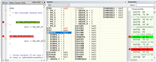
I´m working with custom board to implement two switch buttons, S1 (P0.4) and S2 (P0.1), I cloned S1 (SW6) to S2 to implement it. I see in the HAL_ISR_FUNCTION( halKeyPort0Isr, P0INT_VECTOR ) and special registers also (with IAR Registers Panel) that when I pressed S1 and S2 the respective code associated with each works (hits) to some extent in the code.
I observing, using breakpoints, that in the HalKeyPoll for both buttons the lines HAL_PUSH_BUTTON1() and HAL_PUSH_BUTTON2() are reached. Its cause the Key values 0x20 (correct value) and 0x60 (0x20 + 0x040). After it both buttons provoke the same effects in the application, the lines are simultaneous reached keys & HAL_KEY_SW_6 and keys & HAL_KEY_SW_7.
I no have idea how to fix it. Someone, please can help me?
Note: I using Z-Stack Home 1.2.2a.44539, after implement it I´ll upgrade to Z-Stack 3.0.1.
Bellow I including all those configuration that have correlation on the S1 and S2 (hal_board_cfg.h, hal_key.c, hal_key.h and OnBoard.c)
hal_board_cfg.h
/* S1 */
#define PUSH1_BV BV(4)
#define PUSH1_SBIT P0_4
/* S2 */
#define PUSH2_BV BV(1)
#define PUSH2_SBIT P0_1
#define PUSH1_POLARITY ACTIVE_HIGH
#define PUSH2_POLARITY ACTIVE_HIGH
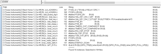
hal_key.h
/* Interrupt option - Enable or disable */
#define HAL_KEY_INTERRUPT_DISABLE 0x00
#define HAL_KEY_INTERRUPT_ENABLE 0x01
/* Key state - shift or nornal */
#define HAL_KEY_STATE_NORMAL 0x00
#define HAL_KEY_STATE_SHIFT 0x01
#define HAL_KEY_SW_1 0x01 // Joystick up
#define HAL_KEY_SW_2 0x02 // Joystick right
#define HAL_KEY_SW_5 0x04 // Joystick center
#define HAL_KEY_SW_4 0x10 // Joystick left
#define HAL_KEY_SW_3 0x08 // Joystick down ant 10
#define HAL_KEY_SW_6 0x20 // Button S2
#define HAL_KEY_SW_7 0x40 // Button S1
hal_key.c
/**************************************************************************************************
* @fn HalKeyConfig
*
* @brief Configure the Key serivce
*
* @param interruptEnable - TRUE/FALSE, enable/disable interrupt
* cback - pointer to the CallBack function
*
* @return None
**************************************************************************************************/
void HalKeyConfig (bool interruptEnable, halKeyCBack_t cback)
{
/* Enable/Disable Interrupt or */
Hal_KeyIntEnable = interruptEnable;
/* Register the callback fucntion */
pHalKeyProcessFunction = cback;
/* Determine if interrupt is enable or not */
if (Hal_KeyIntEnable)
{
/* Rising/Falling edge configuratinn */
PICTL &= ~(HAL_KEY_SW_6_EDGEBIT); /* Clear the edge bit */
/* For falling edge, the bit must be set. */
#if (HAL_KEY_SW_6_EDGE == HAL_KEY_FALLING_EDGE)
PICTL |= HAL_KEY_SW_6_EDGEBIT;
#endif
/* Interrupt configuration:
* - Enable interrupt generation at the port
* - Enable CPU interrupt
* - Clear any pending interrupt
*/
HAL_KEY_SW_6_ICTL |= HAL_KEY_SW_6_ICTLBIT;
HAL_KEY_SW_6_IEN |= HAL_KEY_SW_6_IENBIT;
HAL_KEY_SW_6_PXIFG = ~(HAL_KEY_SW_6_BIT);
/* Rising/Falling edge configuratinn */
PICTL &= ~(HAL_KEY_SW_7_EDGEBIT); /* Clear the edge bit */
/* For falling edge, the bit must be set. */
#if (HAL_KEY_SW_7_EDGE == HAL_KEY_FALLING_EDGE)
PICTL |= HAL_KEY_SW_7_EDGEBIT;
#endif
HAL_KEY_SW_7_ICTL |= HAL_KEY_SW_7_ICTLBIT;
HAL_KEY_SW_7_IEN |= HAL_KEY_SW_7_IENBIT;
HAL_KEY_SW_7_PXIFG = ~(HAL_KEY_SW_7_BIT);
/* Rising/Falling edge configuratinn */
/* Interrupt configuration:
* - Enable interrupt generation at the port
* - Enable CPU interrupt
* - Clear any pending interrupt
*/
/* Do this only after the hal_key is configured - to work with sleep stuff */
if (HalKeyConfigured == TRUE)
{
osal_stop_timerEx(Hal_TaskID, HAL_KEY_EVENT); /* Cancel polling if active */
}
}
else /* Interrupts NOT enabled */
{
//HAL_KEY_SW_6_ICTL &= ~(HAL_KEY_SW_6_ICTLBIT); /* don't generate interrupt */
HAL_KEY_SW_6_IEN &= ~(HAL_KEY_SW_6_IENBIT); /* Clear interrupt enable bit */
osal_set_event(Hal_TaskID, HAL_KEY_EVENT);
//HAL_KEY_SW_7_ICTL &= ~(HAL_KEY_SW_7_ICTLBIT); /* don't generate interrupt */
HAL_KEY_SW_7_IEN &= ~(HAL_KEY_SW_7_IENBIT); /* Clear interrupt enable bit */
osal_set_event(Hal_TaskID, HAL_KEY_EVENT);
}
/* Key now is configured */
HalKeyConfigured = TRUE;
}
/**************************************************************************************************
* @fn HalKeyRead
*
* @brief Read the current value of a key
*
* @param None
*
* @return keys - current keys status
**************************************************************************************************/
uint8 HalKeyRead ( void )
{
uint8 keys = 0;
if (HAL_PUSH_BUTTON1())
{
keys |= HAL_KEY_SW_6;
}
if (HAL_PUSH_BUTTON2())
{
keys |= HAL_KEY_SW_7;
}
return keys;
}
/**************************************************************************************************
* @fn HalKeyPoll
*
* @brief Called by hal_driver to poll the keys
*
* @param None
*
* @return None
**************************************************************************************************/
void HalKeyPoll (void)
{
uint8 keys = 0;
/* If interrupts are not enabled, previous key status and current key status
* are compared to find out if a key has changed status.
*/
if (!Hal_KeyIntEnable)
{
if (keys == halKeySavedKeys)
{
/* Exit - since no keys have changed */
return;
}
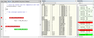
/* Store the current keys for comparation next time */
halKeySavedKeys = keys;
}
else
{
/* Key interrupt handled here */
}
if (HAL_PUSH_BUTTON1())
{
keys |= HAL_KEY_SW_6;
}
if (HAL_PUSH_BUTTON2())
{
keys |= HAL_KEY_SW_7;
}
/* Invoke Callback if new keys were depressed */
if (keys && (pHalKeyProcessFunction))
{
(pHalKeyProcessFunction) (keys, HAL_KEY_STATE_NORMAL);
}
}
/**************************************************************************************************
* @fn halProcessKeyInterrupt
*
* @brief Checks to see if it's a valid key interrupt, saves interrupt driven key states for
* processing by HalKeyRead(), and debounces keys by scheduling HalKeyRead() 25ms later.
*
* @param
*
* @return
**************************************************************************************************/
void halProcessKeyInterrupt (void)
{
bool valid=FALSE;
if (HAL_KEY_SW_6_PXIFG & HAL_KEY_SW_6_BIT) /* Interrupt Flag has been set */
{
HAL_KEY_SW_6_PXIFG = ~(HAL_KEY_SW_6_BIT); /* Clear Interrupt Flag */
valid = TRUE;
}
if (HAL_KEY_SW_7_PXIFG & HAL_KEY_SW_7_BIT) /* Interrupt Flag has been set */
{
HAL_KEY_SW_7_PXIFG = ~(HAL_KEY_SW_7_BIT); /* Clear Interrupt Flag */
valid = TRUE;
}
if (valid)
{
osal_start_timerEx (Hal_TaskID, HAL_KEY_EVENT, HAL_KEY_DEBOUNCE_VALUE);
}
}
OnBoard.c
void OnBoard_KeyCallback ( uint8 keys, uint8 state )
{
uint8 shift;
(void)state;
shift = (keys & HAL_KEY_SW_6) ? true : false;
// shift = (keys & HAL_KEY_SW_7) ? true : false;
if ( OnBoard_SendKeys( keys, shift ) != ZSuccess )
{
// Process SW1 here
if ( keys & HAL_KEY_SW_1 ) // Switch 1
{
}
// Process SW2 here
if ( keys & HAL_KEY_SW_2 ) // Switch 2
{
}
// Process SW3 here
if ( keys & HAL_KEY_SW_3 ) // Switch 3
{
}
// Process SW4 here
if ( keys & HAL_KEY_SW_4 ) // Switch 4
{
}
// Process SW5 here
if ( keys & HAL_KEY_SW_5 ) // Switch 5
{
}
// Process SW6 here
if ( keys & HAL_KEY_SW_6 ) // Switch 6
{
}
// Process SW7 here
if ( keys & HAL_KEY_SW_7 ) // Switch 7
{
}
}
}