The AM62x SK-EVM has two 8-position DIP switches to set the SoC boot mode and related parameters. How do these switches correspond to the boot mode pins documented in the TRM?
This thread has been locked.
If you have a related question, please click the "Ask a related question" button in the top right corner. The newly created question will be automatically linked to this question.
The AM62x SK-EVM has two 8-position DIP switches to set the SoC boot mode and related parameters. How do these switches correspond to the boot mode pins documented in the TRM?
You’ll need to look at the SK-EVM’s schematics in order to map the boot mode pins documented in the AM62x TRM to the DIP switches on the SK-EVM. Please follow the steps described below:
1. The AM62x SK-EVM's schematics can be found at https://www.ti.com/tool/SK-AM62 -> Design files -> SK-AM62 Design File Package — SPRR448.ZIP (65345 KB). Download this file and unzip it, and the schematics is located at sprr448\E3 revision\Schematic\PROC114E3_SCH.pdf.
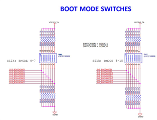
2. Open the schematics PDF file and locate the picture below:
3. Notice that SYS BOOTMODE0 is connected to SW1, position 1, and so on.
4. From the TRM, locate the BOOTMODE pins tables:
5. Now you can map the BOOTMODE pin settings provided by the TRM to the DIP switch positions on the SK-EVM, for a certain PLL clock and boot mode. For example, refer to the table below for setting the PLL clock to 25MHz and the boot mode to SD card boot:
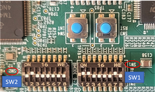
6. Finally the DIP switches on the SK-EVM can be physically set as shown below (note the positions of the 2 DIP switches on the board):
Refer to the AM62x Linux Academy for more boot mode settings.