How to execute code from external memory using M4F Core?

This thread has been locked.
If you have a related question, please click the "Ask a related question" button in the top right corner. The newly created question will be automatically linked to this question.
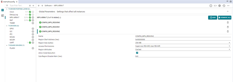
To execute code from external memory using M4F, specify the Memory region in linker.cmd to load and run program also add RAT & MPU configuration in example.syscfg file. Those changes are required because M4F micro-controller core is natively 32b processor. A dedicated RAT module is added to allow M4F processor to access full 36b common SoC address map.
The steps needed to execute code from external memory
${SDK path}\examples\hello_world\am62x-sk\m4fss0-0_freertos
The explanations of each steps is given below:
/* make sure below retain is there in your linker command file, it keeps the vector table in the final binary */
--retain="*(.vectors)"
/* This is the stack that is used by code running within main()
 * In case of NORTOS,
 * - This means all the code outside of ISR uses this stack
 * In case of FreeRTOS
 * - This means all the code until vTaskStartScheduler() is called in main()
 *   uses this stack.
 * - After vTaskStartScheduler() each task created in FreeRTOS has its own stack
 */
--stack_size=16384
/* This is the heap size for malloc() API in NORTOS and FreeRTOS
 * This is also the heap used by pvPortMalloc in FreeRTOS
 */
--heap_size=32768


SECTIONS
{
    /* This has the M4F entry point and vector table, this MUST be at 0x0 */
    .vectors:{} palign(8) > M4F_VECS

    .text: 	 {} palign(8) > DDR_1     /* This is where code resides */

    .bss:    {} palign(8) > DDR_1     /* This is where uninitialized globals go */
    RUN_START(__BSS_START)
    RUN_END(__BSS_END)

    .data:   {} palign(8) > DDR_1     /* This is where initialized globals and static go */
    .rodata: {} palign(8) > DDR_1     /* This is where const's go */
    .sysmem: {} palign(8) > DDR_1     /* This is where the malloc heap goes */
    .stack:  {} palign(8) > DDR_1     /* This is where the main() stack goes */

    GROUP {
        /* This is the resource table used by linux to know where the IPC "VRINGs" are located */
        .resource_table: {} palign(4096)
    } > DDR_0

    /* Sections needed for C++ projects */
    .ARM.exidx:     {} palign(8) > DDR_1  /* Needed for C++ exception handling */
    .init_array:    {} palign(8) > DDR_1  /* Contains function pointers called before main */
    .fini_array:    {} palign(8) > DDR_1  /* Contains function pointers called after main */
}

MEMORY
{
    M4F_VECS : ORIGIN = 0x00000000 , LENGTH = 0x00000200
    M4F_IRAM : ORIGIN = 0x00000200 , LENGTH = 0x0002FE00
    M4F_DRAM : ORIGIN = 0x00030000 , LENGTH = 0x00010000

    /* when using multi-core application's i.e more than one R5F/M4F active, make sure
     * this memory does not overlap with R5F's
     */
    /* Resource table must be placed at the start of DDR_0 when M4 core is early booting with Linux */
    DDR_0       : ORIGIN = 0x9CC00000 , LENGTH = 0x1000
    DDR_1       : ORIGIN = 0x9CB00000 , LENGTH = 0x100000

}
Sections Explanation :
The code is a linker script for a system that uses the ARM Cortex-M4F microcontroller. A linker script is used to specify the memory layout of the system, and it tells the linker where to place different sections of code and data in memory.
The linker script defines several sections such as:
It assigns these sections to different memory regions (DDR_1, DDR_0) in the system. The `.resource_table` section is used by Linux to locate the IPC "VRINGs" in memory, and it is assigned to the DDR_0 memory region.
Additionally, the script also defines sections for C++ projects, such as `.ARM.exidx`, `.init_array`, and `.fini_array`. These sections are used for exception handling and initialization/cleanup of C++ objects and assigned to the DDR_1 memory region.
The script uses the "GROUP" and "RUN_START"/"RUN_END" commands to group sections together and assign specific memory addresses to them. The "palign" command is used to specify the alignment for each section.
The script uses the command `> DDR_1` to place the sections in DDR_1 memory and `> DDR_0` to place them in DDR_0 memory.
The script also assigns specific memory addresses to the sections such as `.vectors`, `.text`, `.bss`, `.data`, `.rodata`, `.sysmem`, and `.stack`, this way the system knows where the sections are located in the memory.
It also uses the `RUN_START(__BSS_START)` and `RUN_END(__BSS_END)` to specify the starting and ending addresses of the `.bss` section.
MEMORY Explanation:
The above code is a memory map for a system that uses the ARM Cortex-M4F microcontroller. The memory map defines the different memory regions of the system and their specific memory addresses.
It defines four memory regions:
`M4F_VECS`: This is the region where the M4F's entry point and vector table are located, at an origin of 0x00000000 and with a length of 0x00000200.`M4F_IRAM`: This is the region where the instruction RAM is located, at an origin of 0x00000200 and with a length of 0x0002FE00.`M4F_DRAM`: This is the region where the data RAM is located, at an origin of 0x00030000 and with a length of 0x00010000.`DDR_0`: This is the region for the DDR_0 memory, at an origin of 0x9CC00000 and with a length of 0x1000.`DDR_1`: This is the region for the DDR_1 memory, at an origin of 0x9CB00000 and with a length of 0x100000.It is specified that when using a multi-core application, such as more than one R5F/M4F active, make sure this memory does not overlap with R5F's.
It also specifies that the resource table must be placed at the start of DDR_0 when M4 core is early booting with Linux.
The memory regions' origins and lengths are defined in hexadecimal notation. The memory map is used to ensure that the different sections defined in the linker script are placed in the correct memory regions and at the correct memory addresses.
More information about when to configure the RAT, and how to use translated addresses, are in the FAQ Updating the Region-based Address Translation (RAT) Settings.
RAT Configuration details in MCU+SDK User Guide : https://software-dl.ti.com/mcu-plus-sdk/esd/AM62X/08_05_00_14/exports/docs/api_guide_am62x/KERNEL_DPL_ADDR_TRANSLATE_PAGE.html
Region-based Address Translation (RAT) is a memory management feature in the AM62x SOC that allows for the mapping of memory regions to specific memory addresses. This allows for the creation of multiple virtual memory spaces that can be used by different components and subsystems of the SoC.
RAT uses a table of memory regions and corresponding memory addresses to perform the translation. Each region is defined by a start address, an end address, and a set of attributes that specify the access permissions and other properties of the region.
RAT can be used to create multiple virtual memory spaces, each with their own set of memory regions. This allows for the isolation of different components and subsystems, and provides a way to control access to memory resources.
For detailed Description please refer to section 9.2.1 of TRM. AM62x TRM
How to Configure RAT:
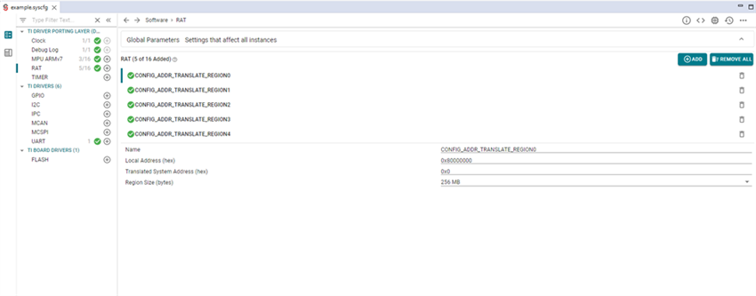
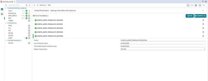
• Change the size of CONFIG_ADDR_TRANSLATE_REGION_0 from 512MB to 256MB.

• Add a new RAT region CONFIG_ADDR_TRANSLATE_REGION_4 as defined in screenshot below.

A Memory Protection Unit (MPU) is a module used to modify the memory types and attributes as defined in a processor’s memory ordering model. The MPU is specific to each core in the system and can only modify the memory ordering model of the CPU to which it is attached.

Example Projects :
I have attached example projects of Hello World M4F for your reference .
M4F Hello World Code :