Part Number: AM6442
Other Parts Discussed in Thread: TMDS243EVM, TMDS243DC01EVM, TMDS64DC01EVM, LP-AM243, BP-AM2BLDCSERVO, BOOSTXL-IOLINKM-8, TMS320VC5507, TUSB320, AM625, AM62P-Q1, TUSB321, AUDIO-AM62D-EVM, AM2432, ISOUSB211, AM623
Hi TI Experts,
I have the below queries regarding implementation of USB interface
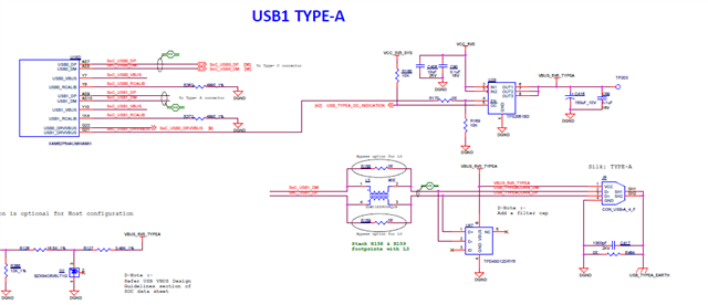
1. Supported USB interface configuration
2. Is VBUS connection required for Host configuration or Device configuration
3. Can I have the VBUS supply input connected when the SoC power supply is switched off
4. Is there a power sequencing requirement for VBUS
5. Can I connect 5V input from the USB connector directly to VBUS
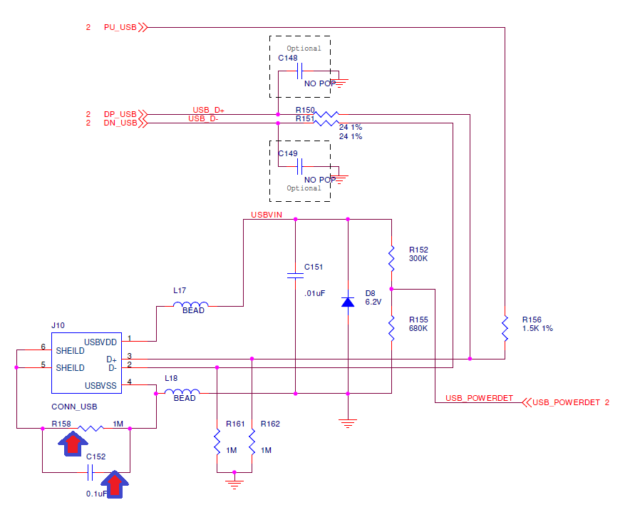
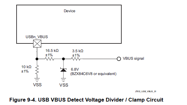
6. Recommended VBUS supply voltage divider
7. SOC VBUS input voltage range and Zener diode connection
8. Supported USB Backup bootmode configuration.
9. Recommended USB RCALIB resistor
10. How to deal with the USB unused pins
11. Is the USB0_ID connection required for Host configuration or Device configuration.
12. Power supply switching and protection when the SOC is configured as USB Host
13. Are these recommendations valid for other Sitara processors or MCUs?
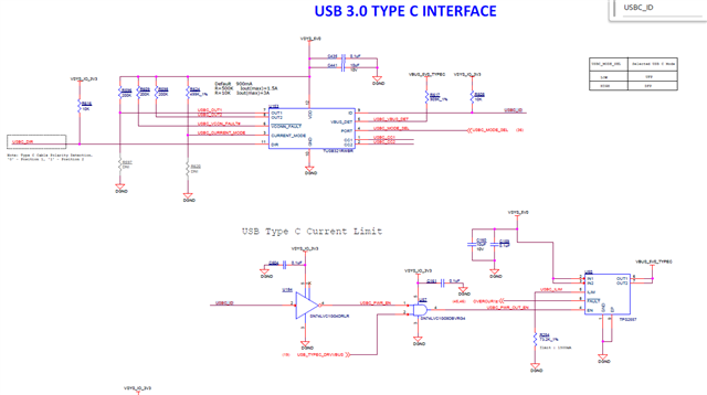
14. Do you have some recommendations on the Type-C implementation.
15. Can I use 3.4K instead of 3.5K.
https://www.ti.com/lit/wp/slyy105/slyy105.pdf
16. Do the differential signal pins (USB, etc.) have the capabilities to adjust the swing of the voltage?
Let me know your thoughts.