This thread has been locked.

If you have a related question, please click the "Ask a related question" button in the top right corner. The newly created question will be automatically linked to this question.

LMC6484: Output Resistance

Part Number: LMC6484

The analysis you have provided does not seem to line up with the results from physical testing.

From your simulations, the LMC6474, the rise time of the output is ~5us however, given that MAX1230 ADC acquisition time is <0.6us, this would result in ADC output being nowhere near 5V - we are seeing around 4.7V when 5V is applied.

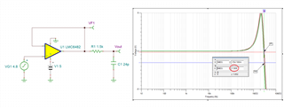
I have simulated the sample-hold function with 0.6us pulse applied to the switch to represent the acquisition and the Vout reaches 5V well within this time.

I still dont know why we are seeing a drop in ADC output i.e. when we apply 4.9V DC to the input the output is around 4.7V...

(both simulations produce the same results)


  • Kiran,

    You seem to refer to some previous tread for analysis we provided but I do not see here any of the info you refer to.

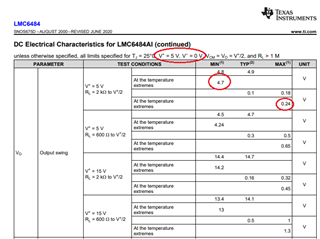
    Having said that, even though LMC6484 input common-mode voltage linear range extends from rail-to-rail, this is NOT the case for the output range - see below.

    LMC6484 linear output range under 2k load is from 0.24V to 4.7V for Vs=5V (see above) and this is the reason why Vout=4.7V when you apply Vin=4.9V - output of LMC6484 cannot get any closer than 300mV below its positive rail.

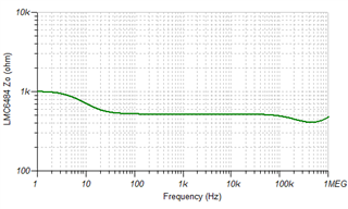
    Also, LMC6484 open-loop output impedance, Zo, is not purely resistive, Ro, but instead changes of frequency.  According to simulation LMC6484 Zo vs frequency graph is shown below.  

    Please review Zo vs Zout material below:

    Open-loop Zo vs Close-loop Zout.ppt

  • We are also seeing this problem at 4.5V as we are seeing flattening of the output as measured by the adc with error exceeding 4%. The output is flat between 4.7V and 4.5V, above 4.7V the output seems to recover and reach the rail. The concern is about what range is affected by this non-linearity.

  • Kiran,

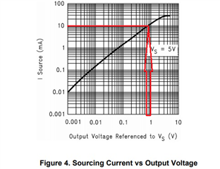
    The output voltage range of any op amp is a function of the output current; in case of LMV6484 minimum output of 4.7V on Vs=5V applies only for 2k load connected to mid-supply (see the default conditions at the top of datasheet table);  Iout = (4.7V-2.5V)/2k = 1.1mA.  For heavier loads you need to consult the graph below.  Thus, for example for Iout=10mA, the output may swing only about 0.8V below positive rail (4.2V on Vs=5V).

  • Thanks for your response.

     The ADC connected to the output has 1.5k input resistance and 24pF sample-hold capacitor therefore I would expect current to be 3.33mA worst case (whilst the capacitor is charging).

    Figure 4 reads 0.2V (reference 0.1V for 1.1mA). If the output will swing to 4.7V for 1.1mA, I would expect 4.6V for 3.33mA. Please confirm.

    Also, how can this be simulated, as my previous simulation does not align with expectation.

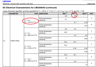
  • All graphs apply to typical specifications at 25C and not a minimum. Thus, for 1.1mA load a typical swing is 0.1V from its rail at 25C (4.9V on Vs=5V), or minimum 0.2V (4.8V) at 25C and a minimum 0.3V (4.7V) over the entire temp range - see table below. 

    For 3.3mA load a typical swing at 25C is about 0.3V from rail but the minimum at 25C and minimum over temp range could be 0.4V and 0.6V, respectively.  Having said that, what is the sampling frequency of the ADC?

    With ADC connected to the output through 1.5k input resistor and 24pF sample-hold capacitor, even at 1MHz sampling rate the impedance of 24pF is already 6.6kohm and becomes higher at lower sampling frequency.  For this reason I believe that the output swing to rail will be closer than your calculation.

  • Sampling rate is around 3MHz. If this is the case, why are we seeing the output flat between 4.7V and 4.5V?

  • At 3MHz sampling rate the total load will be around 3.7k (1.5k +2.2K) BUT your amplitude will be attenuated at Vout due to voltage divider R1||ZC1 - see below (-1.8dB).