This thread has been locked.
If you have a related question, please click the "Ask a related question" button in the top right corner. The newly created question will be automatically linked to this question.
i am operating the fully differential op-amp THS4502 with single supply(5V) to interface it with ADS5424. the input sine wave available has an amplitude of 0-10V . this input is given to the non-inverting input through a voltage divider of suitable values. The inverting terminal is being given a variable voltage reference using LM336(2.5V) and a voltage divider in order to shift the output .
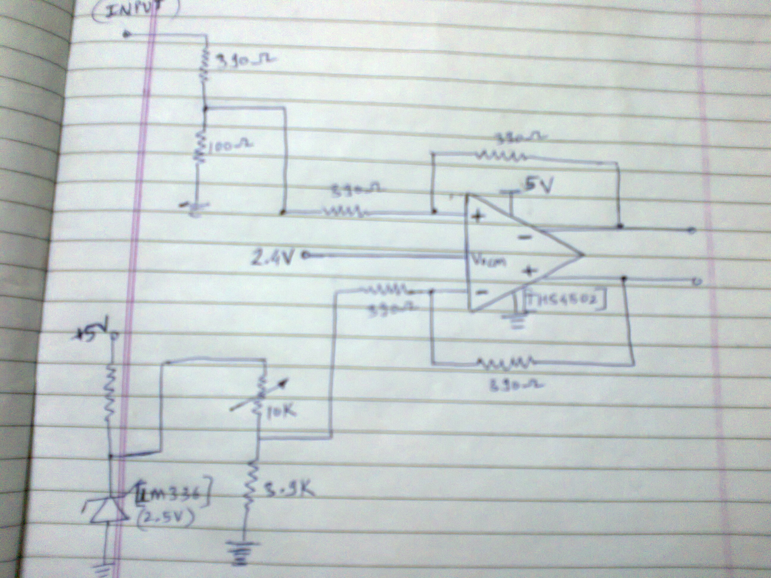
the circuit diagram is attached. also we have externally supplied 2.4V to the Vocm pin.
the problem that i am facing is that the inputs of the op-amp starts drawing excess of current because of which the required voltage drop at the inputs increases and i am not being able to get the required waveform. it has happened twice, once with inverting terminal and once at the non-inverting terminal. and when i remove the op-amp and check the voltages at the voltage dividers(both inverting and non-inverting) they come to be exact as calculated.
So is the op-amp damaged? if yes, then what could be the reason for the damage? if no, what is wrong in the circuit that is causing this excess voltage drop.
So kindly help me deal with this problem. Any kind of assistance will be highly appreciated.
Regards,
nilesh.
Nilesh,
I have several questions about your circuit:
The op amp may not have been damaged - what excess input current are you measuring and how are you measuring the 'excess' current being drawn by the op amp inputs? I might expect damage if the input pins are drawing more than 10-30mA continuous current for extended periods of time (seconds).
Do you mean that the circuit works as expected until some event (input signal change, time, etc)? Do you know what change leads to this issue? When the circuit is in this 'excess current' state, what is the input signal amplitude, pot resistance, voltage at + and - pins, voltage at Vout+ and Vout-? This may help identify the issue.
Is the 0-10V amplitude signal referenced to ground (i.e. bipolar signal)? Is the intention of the circuit to be able to adjust the differential DC offset of the differential output?
I attach a TINA-TI schematic that shows my recommended approach to adding a differential DC offset to the differential output signal. I've assumed that the input signal is bipolar and referenced to ground. I used a THS4501, which is essentially the same as the THS4502, except that the THS4501 input common mode range extends to the negative rail. Please take a look. You can adjust the pot resistance Rpot and see how the differential DC offset changes.
Hi Nilesh,
Thanks for the information. I understand your requirements now.
A fully differential amplifier (FDA) is the same as a regular op amp in that the voltages at the + and - pins are driven to be equal by the negative feedback. Some people like to think of an FDA as two parallel op amps that are each in an inverting configuration. Here is a good application note that discusses FDAs: Fully Differential Amplifiers - sloa054
Part 3 of the below article series directly discusses your application, too:
I've modified the schematic. Based on your schematic, you should be able to make the changes on your board by removing the Zener, shorting out the potentiometer, and changing the resistor values. Please let me know if that helps!