Because of the holidays, TI E2E™ design support forum responses will be delayed from Dec. 25 through Jan. 2. Thank you for your patience.

This thread has been locked.

If you have a related question, please click the "Ask a related question" button in the top right corner. The newly created question will be automatically linked to this question.

AMC1300: Multiple-channel measurement.

Part Number: AMC1300

Please, take a look at the attached draft. I'm using three AMC1300 isolated amplifiers in the showed three-channel voltage measurement circuit, with one unique common reference node.
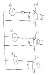
Do you see any problem with that? Note that the three amplifiers are fed by the same power supply. Besides, their inputs are floating in relation to the power pins — I'm doing this because it's clear to me that, since the power voltage is 5 V, the resulting common-mode voltages will never reach the overvoltage detection level.

  • Hi Christos,

    No issue with this from a common-mode input voltage perspective. Care should be taken such that the resistors in the voltage dividers are rated for the voltage and current that will flow through the resistor divider chain, as they are a potential source of a short circuit. 

    As mentioned on the other thread, this cookbook circuit also goes into detail about voltage sensing with low input impedance devices: https://www.ti.com/lit/an/sbaa350/sbaa350.pdf

    Our AMC Voltage Sensing Calculator can be used to help with sense resistor sizing:https://www.ti.com/lit/zip/sbar013

  • Thank you, Alexander!

    My concern with the common voltage has lied in the fact that the referred application note (SBAA350, I had already taken a look at it) doesn't say anything about floating inputs topology. All its explanation is based on how to minimize offset errors resulted from input referencing to the power ground.

    I have another fear: the possibility of, in noisy environments, high-frequency common-mode currents shift common-mode voltage to undesirable levels. I think that ground referencing can minimize this voltage shift...

    Do you think these fears make sense?

    Regards.

    Christos

  • Hi Christos, 

    I missed that you plan on the input voltages floating in regards to the power pins. I would not recommend this for the fears that you cited. With the negative input and GND1 pin tied to neutral, the isolation amplifier's can float along with the high-frequency common-mode current shifts and produce high accuracy measurements as long as the CMTI specification is not violated. 

    You can tie the negative inputs pins, power pins of the devices and power supply ground to the neutral for voltage measurements. 

    For current measurements, each device would require it's own power supply since the measurements will be out of phase and referenced to the high voltage lines. 

    How are you powering the high side of the AMC1300's? 

    The first few pages of this document go over three ways to power the high side of the isolation amplifiers, I assume you are planning on using an isolated transformer? https://www.ti.com/lit/an/slyt810/slyt810.pdf

    Yes, SBAA350 covers how to make high accuracy measurements with low input impedance isolation amplifiers, this topic is not covered in this document.  

  • Thank you again, Alexander!

    Yes, I'm using a small isolated DC/DC converter.

    I think my questions were answered!

    Best regards!