This thread has been locked.

If you have a related question, please click the "Ask a related question" button in the top right corner. The newly created question will be automatically linked to this question.

OPA2277: Abnormal control circuit of constant current source

Part Number: OPA2277

Hi team,

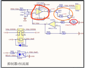
Constant current source circuit sets abnormal current.

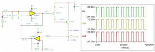
Using oscillograph analysis, the 1 feet of the operational amplifier OPA2277 have the following waveforms, and the waveform vanishes after the 2 foot of the multimeter pen is used.

Want to know how the waveform is generated?

Thank you very much for your help.

Best regards,

  • Hi Zhonghui,

    probably the phase margin of OPAmp is eroded by adding too much phase lag in the feedback loop. You would need to perform a phase stability analysis.

    What else is connected to R405? A cable? How long?

    Kai

  • Hi Zhonghui,

    Want to know how the waveform is generated?

    Your description is not clear. 

    If you mean that the output OPA2277 is generating square wave, then I do not know where it came from. If the output is generating a sinusoidal like waveform, it could be an oscillation as Kai suggested. 

    Could you send us a high resolution schematic? We can check out the stability of the V-to-I converter in simulation (please provide us design requirements). 

    The resistor circled in red is the sensing resistor of the circuit. The constant current is PWM_Y201/Rsense should be the circuit's maximum current, which is following the PWM input voltage. The BJT circled in orange is likely your current supplied transistors. I think that only Q402 is supplying the current as it is configured. In reality, you only need Q402 to get the circuit working. 

    If BJTs are configured as darlington pairs, it does not look right.  YZQ4 connector should be the power source for both transistors. 

    If you have additional questions, please let us know. 

    Best,

    Raymond

  • Hi Zhonghui,

    as feared, your circuit isn't stable:

    zhonghui_opa2277.TSC

    Kai

  • Hi Zhonghui,

    Thanks for Kai's schematic! The V-to-I circuit is now compensated. 

    zhonghui_opa2277 compensated 08252021.TSC

    If you have additional questions, please let us know.

    Best,

    Raymond

  • Hi team,

    Thank you for your detailed answers.

    When the circuit works, the corresponding PWM signal is set according to the required current value, and the relay is connected to 24V through MCU control to output the corresponding current. The abnormality of the above circuit is that the relay is not connected to 24V without applying any PWM signal, and pin 1 of the operational amplifier outputs a 600ms square wave signal of high level 4V and low level - 15V

    If R403 is removed, the signal still exists. If R406 is removed, the signal becomes a 600ms square wave signal with a high level of 14.8V and a low level of - 15V. It feels like a comparator composed of pins 1, 2 and 3 of the operational amplifier, so as to output high and low levels. If the two pins of TIP41C are measured with an oscilloscope, there will be a 20ms sine wave signal, but the amplitude is small, about 500mv, because the output current needs heat dissipation, A 3cm high radiator is fixed on TIP41C.

    Best regards,

  • Hi Zhonghui,

    My speculation is that there is a problematic relay in 24Vdc supplies. I think that relay may be still momentarily or partially On when you did the test (MUC turned if off). The "sticky" relay contact will be completely disconnected from the power when the measured signal is gone or vanished. You may have a time window that the V-to-I circuit is still partially powered when the MCU is turned off. 

    It is possible that U481 opto could be "bad" as well, but poor contacts in relay will be more likely. By the way, how is YZQ1 node or pin4 in U481 is biased. 

    Best,

    Raymond 

  • Hi Zhonghui,

    please note that your circuit has no reasonable DC operating point with an input voltage of 0V:

    Kai

  • Hi team,

    Thank you for your help.

    For the relay problem mentioned just now, the relay in the schematic diagram controls the connection between the constant current source circuit and 24V. In fact, when the same circuit board is started up to an abnormal problem, the single chip microcomputer pin controlling the connection and disconnection of the relay has never been pulled down, that is to say, the relay will not be opened unless we manually control the loading of current (we send instructions through the upper computer), In addition, this phenomenon is reflected in that the actually measured current value (that is, the ad pin of MCU is connected through pin 7 of the operational amplifier) is abnormal. For example, I set 50mA, but the actually displayed 87ma. When the constant current source is connected in series with the current gear of the multimeter, the measured current value is 50mA, that is, the ad voltage value of pin 7 is wrong. Through software debugging, it is found that the actually collected ad value is indeed the value corresponding to 87ma.

    Strangely, if the value of ad pin (pin 7) is measured with a multimeter, the measured value immediately returns to normal. After touching pin 7 with a wire without a multimeter, the measured value and the set value are the same( Replacing MCU does not work).

    Best regards,

  • Hi Zhonghui,

    have you already added Raymond's phase lead compensation scheme?

    Also, I'm a bit confused about R405. You told that the circuit is a current source. But what about R405? Is it permanently installed?

    And how do you plan to manage the DC operation point issue at zero input voltage?

    Please tell a bit more about your application. Why is the 24V supply voltage needed? What is the purpose of the relays?

    What is the load of current source? And is a cable involved?

    Kai

  • Hi Zhonghui,

    It was my mistake. you are running in dual supply voltage. 

    Best,

    Raymond

  • Hi Zhonghui,

    I am going to close this inquiry. If you are able to provide us additional clues, we may be able to take look at the issues again. 

    If you have additional questions, you may still open the thread. 

    Best,

    Raymond