This thread has been locked.

If you have a related question, please click the "Ask a related question" button in the top right corner. The newly created question will be automatically linked to this question.

THS4041-Q1: TI solution suggestion

Part Number: THS4041-Q1
Other Parts Discussed in Thread: THS4041, LM7171, THS4061, LM6171

Dear Team,

I am looking for a TI part replacement for Linear PN LT1363, I found the replacement in TI website : THS4041-Q1


Can you please help me suggest if this can be good replacement? If not, could you suggest suitable solution for me?

Many Thanks,

Jimmy

  • Hi Jimmy,

    this depends on what you want from the LT1363. Is it the "all capacitive load drive" capability? Then the THS4041 might be a good choice. Or do you want the slew rate of 1000V/µs? Then TI offers faster OPAmps.

    Kai

  • Hey Jimmy, 

    The LT1363 is in a class of VFA I call the high transconductance input stage which is two buffers driving a resistor betwen them converting the error signal to current right away. It was developed to give the current feedback shy an voltage feedback option - but does carry with it some pretty poor noise voltage. 

    Anyway, in that time period a few high speed groups also did a few of these on a higher voltage process (not as many as LTC, they were very enamoured of this topology). There is the LM7171 and THS4061 in this internal topology. (oddly, there is also one of the most extreme versions of this hiding inside the microchip product line). 

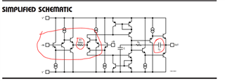
    The Cload drive thing was a LTC only approach where they coupled the comp node to the ouput to put the Cload on the comp pin at high F. No one else was foolish enough to do that as now you have a part whose dynamics are heavily dependent on the Cload. That is always true of course, but here especially so. Oddly, LTC usually shows an internal schematic where that C is circled. You can see the two buffers on the input side as well. This gets the slew rate in a VFA topology. That 500ohm is the input stage transconductance element. 

    Depending on why you need a replacement, there are plenty of better options out there today - a schematic would get that discussion going, 

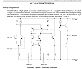
  • And yes, the THS4041 shows a similar Cload capability, its schematic does not show the coupling C from the comp node to the output, but it is likely there. More normal input stage, so the slew rate probably comes from higher quiescent. 

    I never felt the urge to define a part like this, if you know you have a cap load, perhaps use the imbedded integrator app ckt to drive it. 

  • Hello Jimmy,

      For higher slew rate and capacitive load drive ability, LM6171 could be another option. But yes, as Kai and Michael mentioned, we would need more details on which specifications are important for device replacement. 

    Thank you,
    Sima

  • Hi Steffes,

    Thank you for insight and help , also thanks for explaining the mechanism of Fast OPA LT1363,


    So, I have some question,

    1. How do you suggest better immunity against noise , can higher input impedance choice help?
    2. What does Cload drive mean?
    3. I didn’t quite get why coupling comp node to output will affect Cload capability or the overall performance?


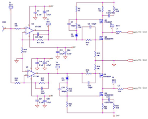
    Below is the part of the circuit (Blanking Circuit), since I can not share full design picture, hope this part of the function can help FAE to understand more and I want to understand more from them.


    So, about our application, basically its used in a Wafer Inspection machine where the Blanking circuit is used to define and control a time duration right after a sample scan is done, to ensure the quality of the scanned image (of the wafer).

    P.S.   Blanking time is supposed to be larger to avoid any black band, distortion or any error in the picture scanned.

    Many Thanks,

    Jimmy

  • Hello Jimmy,

    1. Not too sure the specifics of what you are referring to, but high impedances/input resistors will increase overall system noise. 

    2. CLoad means the amount of capacitance at the output of the amplifier. Some amplifiers are designed specifically to drive higher capacitive loads, but will decrease overall system bandwidth. 

    3. Not an expert on this, maybe Michael can expand or correct the following. The capacitor acts as internal compensation which is critical due to the introduction of the external load capacitor. It improves overall stability of the amplifier (prevents oscillation and ringing), by "slowing down" the amplifier. The additional zero compensates the pole created by the RC output stage which increases phase margin. When Michael mentioned this affecting overall performance, I believe he was talking about that these types of amplifiers are limited in design compared to other voltage/current feedback amplifiers. It adversely affects overall slew rate and bandwidth due to this coupling capacitor to gain the benefit of driving very high capacitive loads. 

       Thank you for sharing details of the application and providing a schematic. Would you also be able to share the input signal characteristics (frequency, rise time if not a sine wave, and voltage range)? The FET push pull stage would suggest that they are not using very high speed signals, and are more concerned about output current and capacitive loading. In that case, Kai and Michael's suggestions would work for this type of application.

    Thank you,

    Sima

  • Hey Jimmy, your schematic is showing a dual channel power driver with FETS inside the loop - driving guns is suggestive. Anyway, where is this question going? Are you trying to replace the LT part for some reason - the stability analysis for these circuits is not trivial and simply looking for "similar" parts is far short of doing a full stability analysis. 

    The Cload idea is you put the load C on the comp node slowing the part way down and holding stability over a wide range of Cload right on output pin at the cost of slew rate and BW (the front page of the THS4041 shows that with closed loop BW contracting fast with Cload).