Other Parts Discussed in Thread: INA826, , TINA-TI
Dear All,
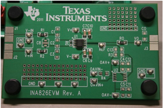
My query was regarding the use of INA826EVM (INA826 Evaluation Board) with a 4-wire load cell, and I just wanted to check whether the following connections are correct, as I wanted to simulate the same before purchasing the module.
System Description:
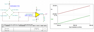
The complete circuit diagram is shown here.

(Figure 1)
The load cell used contains 4 strain gauges at 350 ohms each, the positive and negative excitation to the load cell are between 5V to 7.5V at a sensitivity of 2.0mV/V and 5 N-m is the maximum torque.
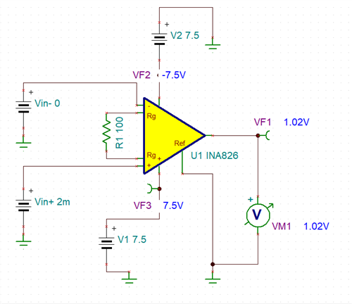
For my application, the output voltage of the load cell is approximately 2 mV (at +5V, -5V excitation), and to connect the same to an ADC, I am attempting to use an INA826 evaluation module set at R_gain = 100 ohms to obtain ~0.99V at VO.
I have also verified the same with TINA-TI software, and the results are shown below.

(Figure 2)

(Figure 3)
My doubts are as follows:
1. I have never used an evaluation board, the discrete resistances and capacitances shown in the circuit schematic are provided in the box, or do I have to order them separately?
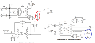
2. The 'REF' point is directly connected to GND via a 0-ohm resistor. I have seen here that doing so is wrong, but the same is correct in the INA826EVM user guide (Figure 2, here). Am I doing something wrong here?
3. The load cell has a floating voltage connection, in some cases, it can also be grounded, but to obtain maximum strain, this is used. I hope the connection here is also correct?
4. There is some slight discrepancy (~20 mV) in the calculated voltage output and the simulated voltage, shown in fig. 3. Can I know the reason for the voltage drop?
Any kind of inputs would be very helpful.
Thanks in advance,
Sincerely,
Sharan


