Other Parts Discussed in Thread: TINA-TI
Hi
I checked three boards and all behave the same wave:
SEL0 SEL1
0 0 high gain Rfb 100k
0 1 lower gain Rfb 10k
1 0 oscillation Rfb 1k
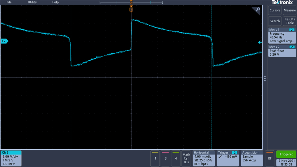
This is the picture of the output.

thanks vadim
This thread has been locked.
If you have a related question, please click the "Ask a related question" button in the top right corner. The newly created question will be automatically linked to this question.
Hi
I checked three boards and all behave the same wave:
SEL0 SEL1
0 0 high gain Rfb 100k
0 1 lower gain Rfb 10k
1 0 oscillation Rfb 1k
This is the picture of the output.

thanks vadim
Hi again Vadim,
For the oscillation, there is a footprint for a feedback capacitor across each gain resistor. You can use it to stabilize the 1kΩ gain based on the input capacitance value of the photodiode you want to simulate. What channel is this output for and what is wrong with it? Was the input a square wave? Does this have to do with your AC coupling?
Hi Sean,
I did not followed the layout. Took a shortcut, because the operating frequency is 500kHz. Presumed not much coupling can happen. I cannot reproduce the oscillation again. today it is just go to 27 mV DC. 00, 01 gives two gains and 10 this small DC. I as well noticed in 00, 01,11 current consumption is 44mA but at 10 it goes to 37mA.
Is there a reason for current to go lower at 10?
thanks vadim
Hi Sean,
I replaced 1 k with 10 k resistor and it is still the same problem, So it seems is not related to feedback. The current decreased to 26 mA from 44mA
thanks vadim
Hi Vadim, I am a bit lost. Is this for our EVM or your new board? If it is a new board, can you post a schematic of the relevant and explain how the amplifier is being driven, and where this waveform was measured?
Please familiarize yourself with this document: https://www.ti.com/lit/an/sboa354/sboa354.pdf
In a trans-impedance amplifier, you need to prevent the circuit's non-inverting gain from having a pole (increasing vs. frequency) that intersects the amplifier's open loop gain (Aol). This will cause the amplifier to oscillate.
Since there is 1.4pF parasitic Cin, a Rf=100k will create such a pole as this. You will need to use a feedback capacitor (Cf=~1pF) in parallel with Rf that will create a flat gain at this intersection frequency. Here is a TINA-TI simulation model. https://www.ti.com/lit/tsc/sbombm8