This thread has been locked.

If you have a related question, please click the "Ask a related question" button in the top right corner. The newly created question will be automatically linked to this question.

INA219:

Part Number: INA219

I'm trying to read both voltage and current of battery by giving some load. My battery voltage when checked with Multimeter is 3.12v but  my code  is giving 2.9v. Which register should I read to get current values?
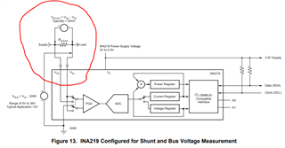
Connection:


Code logic:

     Rshunt_lsb = 0.4

   shuntVoltage_bytes = i2c.readfrom_mem(addr,__REG_SHUNTVOLTAGE, 2) //shunt resistor- 0x01
    shuntVoltage_val = int.from_bytes(shuntVoltage_bytes,'big')
    print("Shunt voltage after calculation:",shunt_voltage*Rshunt_lsb/100)

Output:

Shunt register value:  697
Shunt voltage after calculation: 2.784

Shunt register value:  696
Shunt voltage after calculation:2.7

Is my connection and code proper? How should I calculate current?

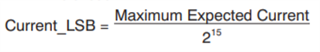
To calculate current

   Current_LSB = 32800

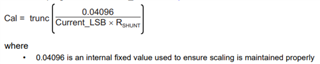
   calibration_register = trunc(0.04096/(Current_LSB * Rshunt_lsb))
   print(calibration_register) //prints 0

   current_register = (shunt_voltage * calibration_register) / 4096  //returns 0 as well

I'm unable to read current, Please help.

Thanks in Advance!

  • Hello Shamita,

    Thanks for the question and using the E2E forum.

    Are you attempting to read the bus voltage or the shunt voltage? It sounds like you're attempting to read the bus voltage, but your code shows you're reading 0x01, which is the shunt voltage. The bus voltage register is actually address 0x02.

    Once you read the correct register for the Voltage reading, there's not really any calculation that needs to be done. If you read register 0x02, the value there should simply be the bus voltage measurement in hex format, and the only calculation that would need to be done is converting it from hex to decimal. For example, if the value in the register were 697h, converting that to decimal would result in 1687d, then multiplying by the standard 4mv LSB would give a bus voltage of 6.748V (which is obviously much higher than what you're expecting, I'm simply showing an example of how to calculate the voltage).

    To calculate the current, it looks as though your programmed value of 32800 for the Current_LSB is probably incorrect. To calculate the Current_LSB, perform this calculation:

    Once you calculate this, you can then calculate and program the Calibration Register, using this formula (based on some of your code, I'm assuming your Rshunt is 0.4Ω):

    Once you've programmed the Calibration Register (0x05), you can read the Current Register. This register will be the value of the current through Rshunt, and you simply need to multiply the decimal equivalent result by your Current_LSB to find the actual current value.

    So essentially, here are the steps required to read your shunt current.

    1. Calculate your Current_LSB
    2. Calculate Cal
    3. Program the Calibration Register (0x05)
    4. Perform a conversion
    5. Read the Current Register (0x04)
    6. Convert Current Register hex result to decimal
    7. Multiply result from step 6 by Current_LSB

    Please let me know if you have any further questions.

    Louis

  • Hey Louis,

    I tried reading bus voltage (0x02), but I'm getting dec value as 2058 and I right shifted to 3 val then multiplied by 0.004, even then I'm getting voltage as 1.0 but actual voltage must be 3.4.

    If I connect +ve point of battery to vin- , only then I get expected voltage. But If make connections to read both voltage and current I get different voltage.

  • Shamita,

    It makes sense that when you connect the positive battery terminal to the IN- pin, you get the expected voltage reading, because the bus voltage register returns the voltage at the IN- pin with respect to GND.

    Can you share a schematic of how you think you're connections are being made? What size is your Rshunt, and how much current are you expecting to be drawn? It's possible that the voltage drop across the shunt is so large that the bus voltage results are different than what you're expecting.

    Louis

  • Hey Louis,

    Below is the picture of my connections:

    I'm reading bus voltage register, but I'm getting very low voltage.

    snippet:

        register_bytes = i2c.readfrom_mem(addr,__REG_BUSVOLTAGE, 2) //0x02
        register_value = int.from_bytes(register_bytes, 'big')
        print("read DEC: ", register_value ,"HEX: ", hex(register_value))
        val = float(register_value >> 3) * 0.004
        print(val)

    I'm expecting voltage to be 3.45v. Is my connection proper??

    Rshunt is 0.4.

    Is this equation     used to program calibration register?

    Thanks,

    Shamita C

  • Shamita,

    I feel I could better help you if I could get a schematic of how you're circuit is wired up. It's difficult to see everything in the picture and it looks like the coupon board you have with  the INA219 on it is not our EVM, so I don't know which pins are IN+ or IN-. From the pics, it looks like your shunt resistor is connected on the low side (assuming red is high side and black is low). If that's the case, your bus voltage results will be very low because, like I mentioned previously, that result comes from the voltage at the IN- pin with respect to GND.

    I'm also not sure why you are shifting the register value to the right 3 bits. The raw value in the Bus Voltage Register is the hex value of the bus voltage, and the only calculations required are to convert it to decimal, then multiply that result by the 4mV LSB to come up with the Bus Voltage result.

    Yes, the equation you pasted is the correct equation to calculate the value to program in to the Calibration Register (once you calculate the Current_LSB first).

    Louis

  • Hi Louis,

    This is my connection picture

    I'm shifting register contents to 3 bits because it is mentioned in datasheet to shift bus register values by 3 bits and multiply by 4mV

  • Shamita,

    I'm sorry but I still can't see the connections being made and am not familiar with the coupon board you're using. Without a schematic I don't know exactly where the signals are going.

    My only suggestion right now is to ensure you're following the suggested connections to measure the bus voltage from figure 13 in the datasheet.

    Secondly, my apologies, I forgot about shifting the bus register 3-bits.

    One thing you could do to help troubleshoot this is probe the IN- pin while you have the shunt connected. After you probe that pin and get the voltage, send a command to trigger a measurement, then read the bus voltage register.

    Could you also do a register dump and show me what all of the registers are reading?

    Louis

  • Shamita,

    I'm going to assume you were able to resolve this issue so I'll close this thread.

    If you have any other questions please don't hesitate to reach back out.

    Louis