Because of the holidays, TI E2E™ design support forum responses will be delayed from Dec. 25 through Jan. 2. Thank you for your patience.

This thread has been locked.

If you have a related question, please click the "Ask a related question" button in the top right corner. The newly created question will be automatically linked to this question.

INA301: Low Side Current Sensing

Part Number: INA301
Other Parts Discussed in Thread: BQ76940, INA300

Dear Sir,

I want to use INA301 for low side current sensing with short circuit detection.

can you please guide me how to implement it?

In many of the TI training videos or articles it's mentioned that if you use it on low side then you won't be able to detect the load to ground short.

Then how AFE bq76940 detects it as it uses current sense amplifier with comparator?

My main goal is to implement short circuit detection using either CSA or op-amp + comparator

Can you please suggest any other alternative?

Regards,

Samruddhi.

  • Hi Samruddhi,

    you can detect a short circuit current with low side sensing, if and only if the short circuit current flows across the low side shunt and sees no other path to ground.

    How to proceed depends on your application, things like supply voltage, load current, short circuit current, response time of short circuit detection, kind of short circuit limitation and many other parameters. Without these parameters no suggestion can be made. So tell us more about your application Relaxed

    Kai

  • Dear Sir,

    Thabk you for response.

    Yes, short circuit current will flow through low side shunt only.

    But then why TI's training video & application notes mentions that load short to ground can't be detected. Current amplifier training video series.

    Will using INA300 or 301 on low side detect the short circuit & give alert to uC as external interrupt?

    I'll finalise System parameters as per different applications. 

    Regards,

    Samruddhi

  • Hi Samruddhi,

    The idea that low-side won’t detect load short to ground refers to the fact that if the load current bypasses the shunt resistor (through a direct short to ground) the current sense amplifier won’t be able to see the load current anymore. This is different from the short circuit scenario that you’re talking about, where the load itself become a short yet the load current still flows through the shunt. And low-side can detect this short circuit current of course.

    I think you mixed the two concepts, and that’s where the confusion is.
    Regards, Guang

  • Dear Sir,

    Ohhh Yes, Correct. Understood. Thank you so much.

    In BMS application for any AFE if short circuit is in the path of BMS then only it's protects. For direct short it doesn't.

    Same for over current protections.

    Now INA300/301 has Vcm = -0.3 to 36V. So for load side i have to design shunt whose voltage drop shouldn't be greater than 300mV correct?

    My SCD protection value should he below 300mV with respect to shunt value & current in amps.

    Regards,

    Samruddhi

  • Hi Samruddhi,

    Yes you’re correct, especially if there is reverse current which causes a negative common mode input voltage relative to ground.

    Also to keep the amplifier in linear range and reduce power dissipated by the shunt resistor, you’ll probably find that the shunt voltage falls far below 300mV naturally.
    Regards, Guang

  • Dear Sir,

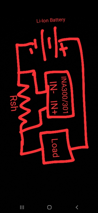
    PFA any li-ion battery system with CSA.

    Battery Voltage 48V26Ah

    Rsh 0.4m-ohm

    Discharge Overcurrent Protection -40A

    Now for SCD as per gain of INA300 I can select the Rlimit of any value of at which I want SCD alert. Correct?

    Eg SCD can be set at 100A. Other design parameters will be taken care of.

    Can you please also verify the IN+ & IN- connections for low side?

    Regards, 

    Samruddhi

  • Hi Samruddhi,

    Using INA300 as an example, we have two knobs that we can turn in order to tune the current threshold. With Rshunt=0.4mOhm and current threshold=100A, the resulting shunt voltage threshold is 0.4*100=40mV. This results in Rlimit=40mV/20uA=2KOhm typical. You can refer to datasheet section 7.3 for a more in-depth discussion of this topic.

    The schematic is fine. With IN+ and IN- connected as shown, the INA’s analog output has the same sign as the differential input. If there is reverse current, the analog output will be stuck to ground.
    Regards, Guang