Hello,
A customer is using the TLV7011DCKT for evaluation.
We are experiencing overshoot and undershoot.
What do you think is wrong?
Best regards,
DDdoor
This thread has been locked.
If you have a related question, please click the "Ask a related question" button in the top right corner. The newly created question will be automatically linked to this question.
Hello DDdoor,
Can you describe the over and undershoot? Or provide a scope photo?
I will assume you are seeing ringing on the output. This is fairly common due to fast output rise and fall times (5ns).
The outputs of a comparator should be treated as a high-speed digital gate, with proper supply bypassing (100nF min) and proper layout techniques. Either poor bypassing or bad layout can cause the supplies to ring on the output transitions, and that can cause oscillations or false triggering.
Also, driving long, thin output traces can also cause ringing. If ringing is a problem, it may be necessary to add a small series resistor (~20 ohms) at the output to dampen the reflections (similar to what is done for SPI or I2C buses).
Hi DDdoor,
the ringing could be the begin of oscillation due to the absence of hysteresis. In any case, in situations with slow input signal and fast comparator, adding hysteresis is heavily recommended. Install a very high ohmic resistor from the +input to the putput of TLV7011 and remove C2! If the supply voltage is noisy, insert a low pass filter into the connection between R2 and the supply voltage.
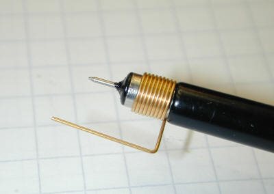
The ringing can also be an scope probe issue. Use such a ground spring:

Probe directly at the right side of R1 with R1 mounted closest to the output of TLV7011. With the spring "prick" the GND pin of TLV7011.
Another cause can be the absence of ground plane. Use at least a local ground plane arround the TLV7011 and mount the decoupling cap and the other components closest to the TLV7011.
Kai
DDoor
please let us know if you require further assistance once you have reviewed Kai's suggestions.
Chuck
Hello DDdoor,,
That is inductive ranging - from less-than-optimal layout or long un-terminated traces...and would be expected. We know it is inductive since the voltages are higher/lower than the applied voltages - so it is being generated inductively. Most likely due to the scope probe ground lead and/or a long ground lead to the comparator.
As Kai shows, placing the scope probe directly across the GND and output pin will reduce the overshoot. The grounds should all be short, direct and to a single point.