Other Parts Discussed in Thread: LM2903B
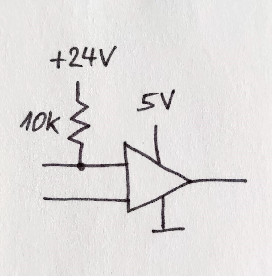
Is this o.k. or will it damage the device?

This thread has been locked.
If you have a related question, please click the "Ask a related question" button in the top right corner. The newly created question will be automatically linked to this question.
Hi Kai,
this is not a normal condition. It occurs only under special circumstances.
Device should only survive this.
To avoid this would be very expensive.
Norbert
Norbert
thanks for your interesting post. Before trying to answer, how frequently do you anticipate this condition occurring and is there any way to increase the 10k resistance to something in the 100k range to further limit the current? As Kai mentioned, you have another resistor off the page that divides this down normally. Maybe that resistor can be scaled up similarly. This would further reduce the current drawn in this fault condition. The challenge we are facing is that we don’t have extensive test data to support this condition. So at best I can give recommendations on how to make this work but I cannot warrant this condition since it’s outside the voltage range.
Chuck
Hi Chuck,
the 10k resistor is not a real resistor. It stands for a part of the circuit with an impedance of about 10k, powered by 24V. The mentioned situation may occur during start up and initialisation of the system for about 1 second.
How do I have to interpret the absolut maximun of +/-10mA for the current into input pins in the data sheet?
Norbert
Thanks for the additional information. The issue is that there are 2 conditions to meet, the current limit you cited and the voltage limit of 7v. Both conditions need to be met. It’s possible that limiting the current to 2.4mA keeps the voltage less than 7v but I’m not sure. I’ll try to get more information tomorrow and get back to you. Regardless it’s good news that this occurs briefly at startup only. Just curious, is your application regularly turned on and off during life of your final product?
Chuck
Norbert
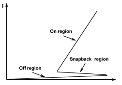
The input pins have an ESD structure that is commonly referred to as a snapback diode. The response looks something like the picture below. It is true that limiting the current with the equivalent of 10k ohms will help protect but the other requirement of remaining less than 7V is also important. The 7V requirement is related to internal structures that are built on a process that is not intended to withstand more than 7V. In the snapback response curve, you can see that high voltages can be maintained at the input before the snapback response occurs. So if the 24V input ramps slowly or spends any measurable amount of time above 7V before being snapped back to the lower potential, damage to the input stage of the comparator can occur. I would not be surprised if the device survived the conditions you mentioned, but we just do not have enough data to be able to warrant such a condition.
Chuck

Hi Chuck,
thanks for this information. My application is a portable device for installation and maintenence of industrial equipement, simulation of differnt sensors. I will realise the prototype as mentioned und undertake excessive tests.
I am very curious how this special protection (instead of the usual esd diode) is realised on the chip. Do you have some more information for me?
Norbert
Hi Norbert,
you might want to see these TI's training videos:
training.ti.com/ti-precision-labs-op-amps-electrical-overstress-introduction
training.ti.com/ti-precision-labs-op-amps-electrical-overstress-overstress-protection
training.ti.com/ti-precision-labs-op-amps-electrical-overstress-testing-robustness
Kai
Norbert
This is a feature that we have been implementing on several of our newer comparators but I am not able to share any additional details on how this is implemented. The benefit is being able to apply voltages up to abs max 7V without power being applied to the device; idea is to minimize impact of power supply sequencing but unfortunately your input is in excess of 7v. Sorry I couldn't provide a better option for you. In your case a part with a standard ESD protection diode would have been better.
Chuck
Hello Norbert,
We haven't heard from you for a while. Do you need any additional information or support?
Best Regards,
Joe
Applications Engineer
Linear Amplifiers Business Unit | Comparators Product Line (CMPS)
All information in this correspondence and in any related correspondence is provided “as is” and “with all faults”, and is subject to TI’s Important Notice (http://www.ti.com/corp/docs/legal/important-notice.shtml)
Hi Joe,
I would highly appreciate to know how your 7V-Protection is realised.
For a safer feeling in this and other applications.
The diode protection is well understood by me and often efficiently applied.
Best Regards,
Norbert Reinhold
Hello Norbert,
Unfortunately this is proprietary and we don't disclose this information.
Best Regards,
Joe
Applications Engineer
Linear Amplifiers Business Unit | Comparators Product Line (CMPS)
All information in this correspondence and in any related correspondence is provided “as is” and “with all faults”, and is subject to TI’s Important Notice (http://www.ti.com/corp/docs/legal/important-notice.shtml)
Good morning Norbert
I understand that you are not satisfied with our support. I am sorry that we cannot provide proprietary information on our ESD implementation on the TLV7022 and unfortunately that device cannot be used for your application. Other than that initial picture, you never provided any additional information about your application. If power consumption is not extremely important in your application, the LM2903B can allow for voltages up to 36V on the input independent of the supply applied and no damage will occur. It is unique function of this family of comparators. Furthermore, as long as one of the inputs of the bipolar input stage is in the recommended operating voltage range, the output of the comparator will be correct. I hope this helps. If you have further questions that need answering, please let us know. I will keep the post open awaiting a response.
Chuck