A related question is a question created from another question. When the related question is created, it will be automatically linked to the original question.
If you have a related question, please click the "Ask a related question" button in the top right corner. The newly created question will be automatically linked to this question.
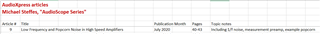
I had addressed this topic in an AudioXpress article referenced here,
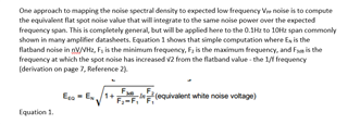
Part of that article maps low frequency 1/f noise to Vpp using this simple equation,
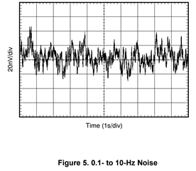
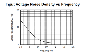
Going to the OPA2211A daasheet, front page plot where the flat part is supposed to be 1.1nV and the 1/f corner is is where that is 1.414*1.1 = 1.55nV - looks like about 22Hz. Putting those numbers into the equation above with F2=10Hz and F1=0.1Hz gives an equivalent flat noise (that will integrated to the same noise power) of 3.7nV/rootHz. Then, taking that times root(10Hz-0.1Hz) gives an integrated RMS noise of 11.6nVrms, then take that times 6 crest factor for an approx. Vpp noise to get 70nVpp
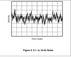
And this plot shows about 70nV peak to peak on this test, so that works - keep in mind, this plot is an individual device measured, there is actually quite a lot of part to part variation in this,
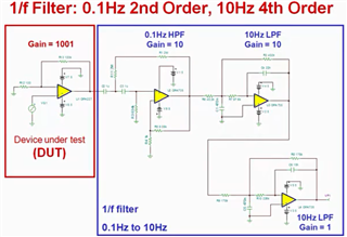
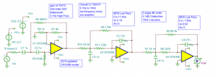
The video Kai referred you to is very good and ends up with the OPA725 as the Low F active filter op amp. That is good for no 1/f noise, but seems really high on flatband noise. And yes, if the DUT is at a gain of 1000 that probably does not matter, but you cannot always put a DUT in that high a gain - for the article, I had done this implementation - Using a gain distributed 4th order MFB low pass in the 2nd two stages has better stop band rejection. The OPA388 is a more modern choice with no 1/f, no drift, and 7nV input noise. I also use this preamp to measure popcorn noise.
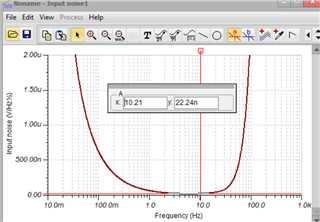
As long as I had that preamp sim file open, here is the input referred voltage noise - this is what DUT needs to exceed by say 10X to get a good mesurement,
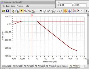
And here is the broadband frequency response to the output, using an MFB design gives you that great stop band rejection to higher F - may not be needed but comes along free with the design,
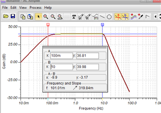
Zooming in on the 0.01Hz to say 100Hz span, this 0.1dB Chebychev for the LP gives a better cuttoff, yes, -3dB at 0.1Hz but flat at 10Hz then cutoff sharply,