This thread has been locked.

If you have a related question, please click the "Ask a related question" button in the top right corner. The newly created question will be automatically linked to this question.

OPA350: what is the bandwidth when configured at 20 gain close loop

Part Number: OPA350

Hi, a few questions regarding using OPA350, thanks!

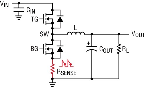
1. is there any concern to use OPA350 for current sensing amplifier for a DCDC converter as shown below. OPA350 datasheet typical application doesn't include current sensing amplifier, so I am concerned.
2. if it is configured as this and the gain is configured to be 20, what is the available bandwidth. The definition of gain-bandwidth-product is open loop, but this is close loop, so i am confused. 

  • Please see my answer below:

    1.  Most op amps, including OPA350, may be used for current sensing for as long as the input voltage does not violate the linear input common-mode voltage range of the op amp.  Also, R1/R2 values should be much higher than Rsense in order to minimize the error caused by some of the current flowing through the input resistors instead of Rsense - for this reason an instrumentation amplifier may be a better choice than the difference amplifier. 

    Having said that, in case the input voltage may go more than 0.3V above/below the supply voltage, the input current should be limited to 10mA or less in order to prevent the damage to ESD protection diodes (e.g. by using series input resistor).  Btw, please be aware that MOS switches shown above may introduce a significant measurement error if their Ron resistance is comparable to Rsense.   

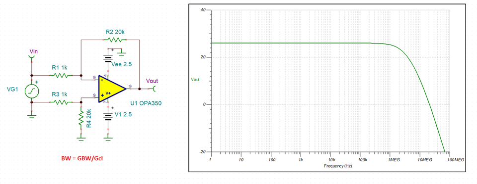
    2.  The bandwidth, BW, of the application is a function of the close-loop gain, Gcl: BW = GBW/Gcl, where GBW is a gain-bandwidth product (38MHz for OPA350).  Thus, for OPA350 in a gain for 20 the effective bandwidth is around 1.9MHz - see simulation below.

  • Kai, I just replied on that thread. Thanks!

  • Hi, Marek,

    Thanks for the reply. 

    Sensing resistor is 5mOhm. how do i choose R1, R2, which is better: R1=1k, R2=20k or  R1=10k, R2=200k (for gain=20).

  • The ratio of sensing resistor, Rsense, to input resistors, R1, determines the current error and in the case of 5mohm it is 0.0005% (5mohm/1k*100%) while value of R2 determines the close-loop gain: Gcl = R2/R1 and therefore also the effective bandwidth: BW = GBW/Gcl.

    R1 of 1k results in 0.0005% error and thus no need to increase any further especially since doing so would result in the higher resistor thermal noise.