Other Parts Discussed in Thread: TINA-TI, , THS3491
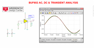
Hi guys, I am simulating the circuit below at Pspice-TI and Tina-TI. I've got the same results at both tools.
I receive 4 analog signals from 50ohms SMA cables with 10Vpp from 1 to 200MHz. The switch 1 selects the channel and the switchs 2 and 3 how much the signal will be attenuate.
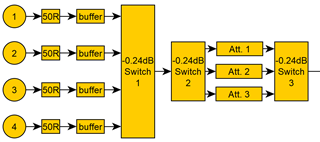
The stages from the circuit are:
V1 - signal source 10Vpp @ 10MHz
R1 - 50ohm load for signal impedance matching
U3 - High impedance buffer BUF602
R2 - Impedance of switchs 1 and 2
T-Pad attenuator for unequal impedances (Zin different from Zout)
R6 - Impedance of switch 3
R7 - 50ohm load of the rest of the circuit (this analog front end circuit will be connected to an ADC)

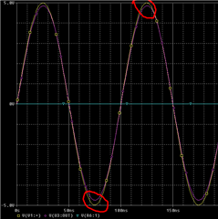
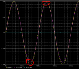
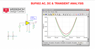
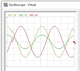
The simulation result shows that the buffer output is not symmetrical.
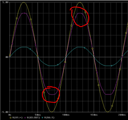
This behaviour is happening because of the attenuator, but do you know guys why?
Thank you,
Rodrigo


