This thread has been locked.

If you have a related question, please click the "Ask a related question" button in the top right corner. The newly created question will be automatically linked to this question.

OPA4172: OPA4172

Part Number: OPA4172

Dear members,

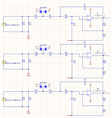
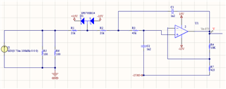
I've used OPA4172 for making a Sallen-Key second order low passs filter. I need to make 4 filters because the input scaling is different among them:

0.075A for Vmax=4000   Vmin=-4000

0.2A for Imax=100   Imin=-100

0.21A for Imax=200   Imin=-200

0.257A for Imax=1286   Imin=-1286

this is the definition of my voltage and current sensors. You can see the design below. 

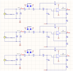
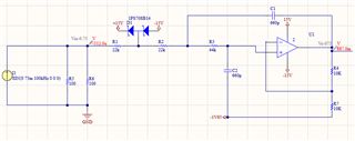
the cut-OFF frequency is 3.5KHz. With simulation I can see that this design is working properly. Now my question is if I can change the design to have one generic for all the scales. I know that I can easily connect them to different ports of the MICRO and then there won't be any problem. But is there any way to have one generic filter for all of them?

Regards

Farzaneh    

  • Hi Farzaneh,

    I'm not sure whether I understand you correctly.

    If you have different sensors and you want to read them (almost) simulataneously at different input ports of µC, you would need a low pass filter for each sensor.

    If you have different sensors and you want to read them one after the other, on the other hand, being willed to wait for the settling time of the low pass filter, you can put a multiplexer in front of the low pass filter and read the output of low pass filter with only one input of micro. All the scalings of the individual channels could then be done in front of the multiplexer. Is this your question?

    Kai

  • Dear Kai,

    I have four different sensors for four different designs. when the first sensor shows  0.75A it means that it is measuring the MAX voltage of 4000V. When the second one shows 0.2A it means that it's measuring the MAX current of 100A. Third one shows 0.21A when it's measuring the MAX current of 200A and the last one when it shows 0.257 it's measuring the max current of 1286A.  

    I dont need to read them simultaneously. What I'm searching is to reduce the number of Micro pins that I need for each one. As I have different scales I need to use one pin for each sensor. I wanna know if I can change the design to one for being able to use less pins of the MICRO. 

    Regards

    Farzaneh

  • Hi Farzaneh,

    Tracking the scalability would require changing the gain of the circuit so that they would scale more closely with each other. If I understand correctly, right now all four of the sallen-key filters look identical no matter which sensor you use. This would be fine but it seems that the MICRO has issues with that.

    Would it be possible for you to make adjustments to the filter's gain? 

    Best Regards,

    Robert Clifton 

  • Hello Robert,

    I should say that is not possible to change the gain. I think there is no way to use less pins of the MICRO in this design. So what I could have done it to make an identical filter circuit for all of them and then the vout of each one slightly changes You can see the last changes below:

    Thanks alot for your time dedication

    Farzaneh 

  • Hi Farzaneh,

    I see you made some slight changes to the design.

    Is there any additional questions you have? 

    Best Regards,

    Robert Clifton

  • Hello Robert,

    I guess I will leave the design just like this for the moment. 

    Thanks for your support

    Farzaneh

  • Hi Farzaneh,

    you could use an input amplifier for every single sensor for the scaling only. At the outputs of these four amplifiers you could mount a 4:1 multiplexer, choosing only one of these four amplifiers' output signals at a time. At the output of multiplexer you could mount your low pass filter and connect the output of low pass filter to only one ADC input of microcontroller.

    Of course, you would need two free pins of microcontroller then to select one of the four input channels. So would end up with two digital output pins of microcontroller and one ADC input of microcontroller. With your original methode, on the other hand, you would need four ADC input pins of microcontroller.

    Kai