This thread has been locked.

If you have a related question, please click the "Ask a related question" button in the top right corner. The newly created question will be automatically linked to this question.

INA303: PWM switching noise

Part Number: INA303
Other Parts Discussed in Thread: INA240

Hello,

I have an INA303 sensing the current through an H-bridge, which switches with a PWM of 20 kHz. The problem is that the output of the INA is very perturbated by the switching noise, yielding an output as follows:

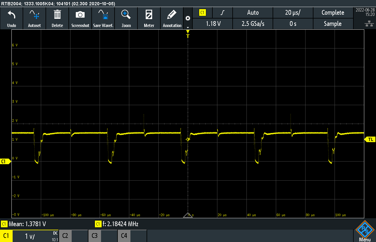
The output is referenced to 1.5V, thus the offset seen.

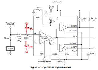
Is there a way to filter the common-mode switching noise out of the INA ?

Thanks,

Federico

  • Hi Frederico,

    what would be the expected signal? A straight line?

    Kai

  • Hi Kai,

    Yes, in that case I'm not outputig enything, so I'd expect a straight line.

    Best,

    Federico

  • Hey Federico,

    Would please send a schematic? Sometimes a large RC on the output can extend the disturbance over time.

    The only way to address this is to use an input filer (combination of a differential and common-mode filters at the inputs). Ideally you want the lowest fc (highest capacitor values) that do not slow down signal acquisition past acceptable BW and also largest Ccm that does not exceed maximum bus load capacitance. It usually better to keep Cfilter (Cdiff) > 10*Ccm to keep the shunt voltage stable as the Ccm settles after every Vcm switch.

    The next step to insert a blanking time into firmware to ignore the output disturbance if possible.

    If cannot get the Vcm disturbance down to acceptable level nor blank it out in firmware, then you will need to switch to an amplifier that is designed to reject fast Vcm switching when sensing in-line motor currents off H-bridge such as INA240 or INA241.

    Hope this makes sense.

    Best,

    Peter

  • Hi Peter,

    thanks for the answer. Here's a schematic of the circuit

    (C237 & C238 are not mounted). The rense resistor is 8mR.

    What would you suggest as a filter in such case ?

    Best,

    Federico

  • Hi Frederico,

    please keep in mind that even the least imbalance of C237 and C238 can totally ruin the awesome common mode rejection of INA303. Because of this, this filter can even do more harm than good, unfotunately. Sometimes even decreasing C236 can improve the situation.

    So, I would start with small capacitances C237 and C238. Firstly 100pF NP0 both, then in a next step 1nF NP0 both, then 10nF NP0 both, and so on. The caps must be state-of-the-art with lowest tolerances and drifts. 1% toleranced caps are available today. Or hand select them by the help of a good cap-meter for best match.

    Another often overlooked issue is imbalance introduced by too long cabling at the inputs. The INA303 should sit closest to the shunt and the shunt closest to the application. This will minimize unwanted (and uneven!) inductances causing dangerous inductive kick backs and bouncing and minimize unwanted (and uneven!) stray capacitances.

    And keep in mind, that choosing a proper signal ground for the INA303 can also minimize the common mode noise seen by the inputs: When the INA303's signal ground is dirty and contaminated by common mode noise, the INA303 can have a way more difficult job to do. So play bit with the signal ground connection of INA303.

    Kai

  • Hey Federico,

    One quick feedback I have is that the DELAY pin should be a 100kΩ to VS as suggested in section 7.3.3 of datasheet.

    The 1uF capacitors are probably making the AC CMRR worse as Kai suggested. As he recommended, I recommend the same: start with C237=C238=open, then 500pF, then 1nF, then 5nF, then 10nF, and 50nF. Also try to use low-tolerance C0G/NPO capacitors to minimize any imbalance in RC constants. 

    Keep in mind that your current differential cutoff frequency is 1/(2*2*PI*10Ω*100nF) = fc = 79.6 kHz, so you could consider increasing C236 up until the required signal BW. Given the motor is switching at 20kHz, you could set fc_differential to 30kHz to 50kHz. This would allow you to increase C238 and C237 to 100nF (because you want C236>10*C238 in order to keep Vsense stable as VCM settles), but you may not want to go higher than 100nF because capacitor tolerance will begin to degrade after this.

    Overall, this is a very tricky circuit to tune because INA303 was not designed to settle quickly after fast VCM switching. First, you don't want to set a fc_differential that is too low and cause Vsense settling issues, but you need to satisfy Cdiff>=10*Ccm. Second, you want to set some common-mode filtering at each pin to attenuate high-frequency Vcm content, but at some point if C237/C238 are too high, then the chances of longer settling times increase because capacitor tolerance will begin to degrade. Larger common-mode RC imbalances mean that it can take longer for C237 and C238 to settle, which translates into longer settling at the output. It is possible to find the right combination of passives that achieve required signal BW, output disturbance amplitude, and settling time, but it will need to be validated over temperature and system population

    Hope this helps.

    Sincerely,

    Peter

  • Hi Peter and Kai,

    Thanks you very much for your feedback, it's most appreciated!

    I will try those tricks and if they don't work, I'll fall back to an amplifier like the INA240 once it's back in stock.

    Best regards,

    Federico