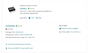
Other Parts Discussed in Thread: TLV9002, TLV9052, TLV9062, DIP-ADAPTER-EVM
I am using the LM10 as a simple differential amplifier. Each input is attached to a copper probe that is essentially 'floating' electrically in a fluid. I am measuring the potential between the two copper probes with this circuit. It works beautifully. The LM10 is optimal because my output cannot exceed 1.8V or I blow out the ADC of the BeagleBone Black MCU we are using. (1.8 V zener's are out of stock EVERYWHERE.) So I power the LM10s with 1.8VDC. The output of the differential amp feeds into a simple non-inverting op amp with 2X gain using an LM10, again powered by 1.8VDC.
Our issue is 60Hz noise on the signal which is not present on our power supply. (The supply voltage rejection is pretty good on these units so I also question if that's where the noise is coming from. Granted this is all on a breadboard currently, no twisted pair or shielding, etc. Sort of a perfect situation for noise that we will address with a PCB and better connections.
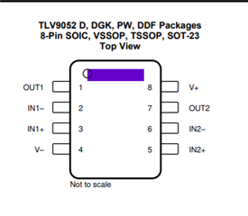
My question however has to do with what do we need to do with pins 8, 1 and 5 on these op amps? We are not using the built-in reference voltages at all. Currently these are all floating. Should they be connected to something and if so, what? Could they introduce some noise?
Thanks!
Walter