This thread has been locked.

If you have a related question, please click the "Ask a related question" button in the top right corner. The newly created question will be automatically linked to this question.

OPA551: Junction temperature

Part Number: OPA551
Other Parts Discussed in Thread: OPA549

Hi Team,

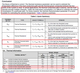
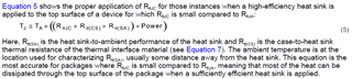
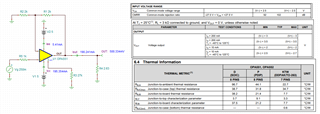
I have questions about the OPA551 datasheet. In page 18, it says that for PDIP package, the thermal resistance is 100 C/W, And on page 4, it says that the thermal resistance for the same package is 44.1 C/W.

Am I missing something? Can you please explain this?

Thank you.

Regards,

Marvin

  • Hi Marvin,

    It looks like that there are typos in the calculation shown on page 18.  

    Based on the Figure 35 of SOA, the datasheet's example is operating in a safe region at Tamb = 40C. 

    Over the years, the thermal and IC's junction temperature thermal model have been improved. In order to estimate the junction temperature more accurately, it will be better to use Ψ thermal model to estimate junction temperature as shown in the image below, also see the attached link. 

    If you have additional questions, please let us know. 

    https://www.ti.com/lit/an/slua844b/slua844b.pdf?ts=1658162137753&ref_url=https%253A%252F%252Fwww.google.com%252F

    Best,

    Raymond

  • Hi Raymond,

    I have further question.

    1. "junction to board" refers to the PCB correct?
    2. "junction to top", does the "top" refers to the top part of the package?
    3. Are you saying that I should use "characterization parameter" and not the "thermal resistance" to calculate the junction temperature? Is it applicable only to OPA551? In OPA549's datasheet, no "characterization parameter" is given, does it mean that I should use "thermal resistance"? 
    4. What are T_c-top and T_B(Usage formula column) in the table-2?
    5. How do I calculate the thermal resistance between the heatsink and air without having the information of the thermal resistance between the top casing of OPA551 and the heatsink? This calculation will enable me to find out the heatsink of an appropriate size for my application. In OPA549 datasheet, the information of thermal resistance between the case and heatsink is given, so I was able to find out the thermal resistance between the air and heatsink using the equation of T_J=T_A + P_D*(Theta_JC + Theta_CH + Theta_HA). This enabled me to buy or make the appropriate size of heatsink.

    Thanks for the help.

    Regards,

    Marvin

  • Hi Marvin,

    1. "junction to board" refers to the PCB correct? yes

    2. "junction to top", does the "top" refers to the top part of the package? yes, 

    3. Is it applicable only to OPA551?

    The article is saying that both thermal models and parameters are correct. However, Psi model will estimate the junction temperature more accurately than R_theta_JA figure. Psi thermal model is evolved more recently. 

    4. What are T_c-top and T_B(Usage formula column) in the table-2?

    Since you are using PDIP package, I would take R_θJC or R_θJB figures instead, since R_θJC is larger, I would take 31.8C/W instead --> to estimate the IC's junction temperature. 

    5. How do I calculate the thermal resistance between the heatsink and air without having the information of the thermal resistance between the top casing of OPA551 and the heatsink?

    You may estimate the junction temperature using the following equation with R_θJC approx. at 1C - 1.25C/W. In this case, the majority of heat dissiplation is conducted through the metal tab via the back of TO-263 package. 

    https://www.ti.com/lit/an/spra953c/spra953c.pdf?ts=1658148855571&ref_url=https%253A%252F%252Fwww.google.com%252F

    If you have additional questions. please let us know. 

    Best,

    Raymond

  • Hi Raymond,

    Just to clarify, is the equation mentioned in item 5 is applicable for TO-263 correct? and Heat sinking is not necessary for PDIP packages, correct?

    The customer requires PDIP for their prototype, Can you tell me how to calculate for the heat sinking for PDIP package?

    Thanks!

    Regards,

    Marvin

  • Hi Marvin,

    The customer requires PDIP for their prototype, Can you tell me how to calculate for the heat sinking for PDIP package?

    You may use the following Psi figures to calculate the junction temperature per a worst case Tamb condition. 

    Yes, no heat sink is needed for PDIP package, but the current and power dissipation ratings are limited. Sometimes, if junction temperature is high for some unknow reasons, customer may bond a heat sink on top of PDIP package with thermal conductive epoxy. 

    I see that your operating is well under the recommended SOA curve. 

    If you have additional questions, please let me know. 

    Best,

    Raymond

  • Hi Raymond,

    I see that your operating is well under the recommended SOA curve.
    Can you explain how did you confirm that the operation is well under the SOA curve? (without the supply voltage, output voltage, and the load conditions given). 
    The customer's lab temperature is about 25C and power dissipation along that SOA curve for 25C is 0.6 W. the application involves power dissipation in OPA551 above 0.6W. 
    In addition, you mentioned previously that for PDIP package, they should use Thermal resistance but in your latest reply, you mentioned using psi figures for PDIP package. Does this mean that they can use both? Can you please clarify? 
     
    Furthermore, can you please share the thermal resistance or psi figures between the epoxy top casing and heat-sink surface?
    Thank you and regards,
    Marvin
  • Hi Marvin,

    the application involves power dissipation in OPA551 above 0.6W. 

    Why not telling us the power dissipation of your application?? Then we would no longer have to guess...

    The standard junction to ambient thermal resistance of a DIP8 package is about 85K/W and the standard junction to ambient thermal resistance of a SOIC8 package is about 100K/W. Mounting a heat sink onto a DIP8 or SOIC8 package doesn't make much sense because a plastic package is no good heat conductor. If you have lots of heat to dissipate then take the OPA551 in the KTW package. That's the usual way to proceed and that's why the OPA551 is sold in the KTW package at all.

    Kai

  • Hi Marvin,

    Can you explain how did you confirm that the operation is well under the SOA curve?

    I was assumed that you are working with an example that is similar to the example in the OPA551's datasheet on p.18 from the initial post. 

    Does this mean that they can use both? Can you please clarify? 

    Yes, you may use either junction estimation method, but the Thermal resistance estimation method may result a slightly higher junction temperature. Since the dissipation power is 0.6W, I do not see that you will have the elevated junction temperature beyond the thermal recommendation in PDIP package. 

    Regarding to last question, please see Kai's reply. 

    If you have additional questions, please let us know. 

    Best,

    Raymond

  • Hi Kai and Raymond,

    Thanks for the support.

    The standard junction to ambient thermal resistance of a DIP8 package is about 85K/W and the standard junction to ambient thermal resistance of a SOIC8 package is about 100K/W.

    Would you kindly tell me where you got this from? Is this from the datasheet? The sudden change from C/W to K/W is also confusing.

    Regards,

    Marvin

  • Hi Marvin, 

    K/W or Degree Kevin/Watt is the SI unit, the absolute thermal resistance unit. In this case, K/W is the same as C/W, where 1 degree Kevin in delta (or change in temperature) is equivalent 1 degree Centigrade in delta per one watt of dissipated energy.

    About the figures, I am not clear...

    Best,

    Raymond

  • Hi Raymond and Kai,

    I finally got the full information from the customer. Here is the full information:

    The supply voltage is +5 and -5 volt. The maximum dc current is 190 mA and they are using a feedback resistor (2.5 ohm) as a load resistor.

    Vo= (1+(R1/R2))Vi

    Here R1=2.5 ohm (feedback resistor)
    So power dissipation inside the PDIP package of OPA551 is P1=(Vs -Vo)* Io.

    Io = 190 mA
    Vs= 5 V
    Vo= 2 V

    Hence P1= 0.57 Watt(power dissipation in the output stage of OPA551)

    In the datasheet, it is mentioned that Vo can't be above 2 volt since 3 volt has to drop somewhere (power transistor) inside the OPA551.

    P2= 6.8 mA(at about 25 C) * 10 volt = 0.068 Watt
    This is the power dissipation somewhere in the input or intermediate stage of OPA551)

    So Ptotal =P1 + P2 = 0.57 Watt + 0.068 Watt = 0.64 Watt. My lab temperature is close to 25C. So, in SOA curve, I can see that there is one curve along which power dissipation is 0.6 Watt at 25 C, but here the power dissipation goes outside the area bound by 0.6 Watt. Please let me know if something is wrong here in my calculations or concepts.

    I am making this on the perf board. This is not the PCB and so I can't use surface mount package of OPA551.

    So, now I want to put a heat-sink on that top casing of PDIP package of OPA551. The top casing(epoxy) is not the good heat conductor). If I have the details of thermal resistance between the top casing and the heatsink surface, I can calculate the thermal resistance between heatsink surface and air and accordingly I can look for a heat-sink.

    I hope this helps.

    Regards, 

    Marvin

  • Hi Marvin, 

    It is not clear what the schematic circuit looks like. Anyway, I extracted some information from the description, it may look like the circuit below, see the attached file. 

    OPA551 DC 2.5Ohm 07282022.TSC

    Assumed that P1 is the power dissipation on the positive side of OPA551 driver and P2 is the power dissipation of the negative side of OPA551 supply rail. 

    P1 = (5-0.5)*195.34mA = 0.879W

    P2 = (5-0.5)*5.41mA = 0.024W

    The total Wattage = P1 + P2 = 0.903W

    From Psi thermal metrics with 21.2 C/W, the heat dissipation of 0.903W will generate Temp rise of 19.1C

    If Tamb = 25C, the junction temperature of OPA551 in PDIP package is approx. 25C + 19.1 = 44.1C. which is ok. 

    If you place a heat sink on top of OPA551 in PDIP package, then the junction temperature should be lower, and will be a better option. 

    If you have additional questions, please let me know. 

    Best,

    Raymond

  • Hi Marvin,

    yes, the schematic is unclear to me too. Can we have a schematic, please?

    Kai