This thread has been locked.

If you have a related question, please click the "Ask a related question" button in the top right corner. The newly created question will be automatically linked to this question.

INA250: INA250A1PWR current sense readings not as expected

Part Number: INA250

Hi TI forums!

We've come across a hiccup while testing some of our newly designed boards. 
Initially we thought it was a FW error when our current readings were not exactly as expected. However on one of our designs we have two of these current sense IC's in series. (The references are not tied together) 

With both ICs were giving different results, it lead us to run some tests and below you can see each IC has set mV offset from the expected reading.


Column D is the expected Reading.  Column F and H are what we're getting. 
We also tested another INA250A1PWR, not shown in this screenshot, that one was getting within 5% of the expected readings. So it is not an issue with the PCB. (Measurements are taken right off pin 9 of IC)

If the ICs are swapped locations on the board the readings follow the IC not board location. 

Any suggestions on where the issue may lie, or do we have a bad batch of parts? 

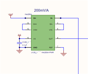
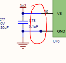
Schem snippets

Thank you for your time!

  • Hi,

    You’re doing all the right things to debug, and explained your findings well.

    The >100mA offset is over datasheet specification. How confident are you about the accuracy of “Power Supply Reading (mA)”, was it read off of the power supply itself? It might be worth checking with a current meter

    Regards, Guang

  • “Power Supply Reading (mA)” is from the power supply display. (using Siglent and Rigol supplies)   And the load is a constant current load after a buck regulator 25V down to 12V. So I am pretty certain that the expected readings are correct, on both ends. 

    Other than testing a large batch of these chips, we're at an impasse.

  • Hi,

    One thing I would recommend is to measure the differential voltage across pins 4/5 and 12/13. A high precision meter is necessary, such as HP3458. And I would set to higher current like 1A or higher so that it is easier to measure. This measurement may provide some clue.

    Maybe I’m just paranoid, but the schematic connection looks a bit odd – one pin shows a dot while the other doesn’t. Are they both connected properly in layout?

    Regards, Guang

  • Haha, you've reopened the internal discussions we've had about those dots. Its how Altium shows stacked pins on a symbol. 

    We will see what we can do about measurements on differential pins. 

  • Hi,

    OK sounds good, please keep us informed of testing results.

    Regards, Guang

  • Hi Guang, 


    I'm helping Arbab with some measurements here. We only have a 5 1/2 digit DMM, however, it operates in a 200 mV mode so I think that will suffice to show the issues (the meter is rated at +/- 0.0115% of measurement).

    With the 2000 and 1000 mA load applied at the 12V out port (rows 40 and 44 in the snippet attached above), I'm measuring 1.949 mV and 0.978 mV across pins 12/13 and 4/5. Over the 2 mR shunt, that results in 0.9745 A and 0.489 A through the shunt. With an input voltage of 25V, I'd expect 0.96 and 0.48 A, that's an error of < 2%, which I'm happy with.

    I re-measured the pin 9 voltage, and measure 234.484 mV and 135.106 mV, which results in 1.172 A and 675 A for the INA250A1. That error is 22% and 41%.

    From this, I see the shunt well within spec, but output is way off. Any ideas?

    Brad.

    PS: here's the copper layout, on 1 oz.

  • Hi Brad,

    With shunt well within spec but output way off, the logical conclusion is that the device itself is defective. Before returning such units for factory verification, can you please check the output pin, as well as IN+ and IN- pins, to make sure they are stable? From the schematic everything looks OK, but just to double check.

    Regards, Guang

  • Thanks Guang, agreed. Do you know of a batch defect issue with these parts? We've seen similar in a few of these parts now, originally thinking our design was off. But if we have to test every part before using them, that will be quite intensive (at present, we'd have to install the parts directly on the application board). Since we use around 40 of these parts in each of our devices, is there any way you could send us a batch that have been confirmed to be operating within spec? 

    I'll check IN+/- early next week and send you the results.

    Brad

  • Hi Brad,

    The parts are 100% tested before being released to distribution, so any batch should perform up to datasheet spec. You could return one or more of the bad ones to us for verification. That way we know for sure if the parts are indeed faulty, or if we need to look at something else.

    To procure additional parts, I recommend try the channel you used first. Unfortunately I couldn’t get hold of any samples, even for a very small quantity.  

    Regards, Guang