This thread has been locked.

If you have a related question, please click the "Ask a related question" button in the top right corner. The newly created question will be automatically linked to this question.

LMH6518: Layout guideline

Part Number: LMH6518
Other Parts Discussed in Thread: LMH6552,

Hi team,

I have a application details want to confirm wiith you while using LMH6518+LMH6552 as the DSO signal chain.

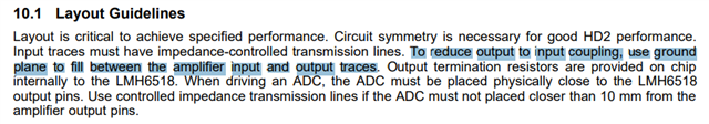
what should I do with the GND cooper in the system, if I just solder the cooper all over the whole signal chain will be better for sheilding or leave the LMG6518 and LMH6552 placement section no GND cooper?

Could you please give some recommendation here?

Thanks

Best regards

Mia Ma

  • Hi Mia,

    Are you referring to adding a ground plane on the signal layer between traces? I am having trouble understanding your question. Could you provide a picture? 

    Best,

    Sam

  • Hi Sam,

    Yes, I want to check the ground plane details, since the EVM PCB material seems limited in the ti.com.

    I would like to know more guideline details about the ground plane for LMH6518 and LMH6552;

    Thanks.

    Best regards

    Mia Ma

  • Hi Mia,

    yes, it's standard design practise to have a solid ground plane and ground fills whereever possible. This will dramatically reduce the input to output coupling and improve the performance of the whole circuit.

    Two points are important then:

    1. Signal traces should be made of impedance-controlled transmission lines. This means that the signal lines must have certain dimensions in terms of width and distances to the surrounding ground fills and the underneath located ground plane. Here is a link which demonstrates what I mean:

    https://www.protoexpress.com/blog/difference-between-microstrip-stripline-pcb/

    Keep in mind that many manufacturers of printed circuit boards don't standardly use a fixed distance between the outer layers and the inner layers of a 4-layer or multi-layer board. You must tell them what distance they shall make.

    2. Ground fills are only effective when you bond them by lots of vias to the underlaying ground plane. Only by this the ground fills are forced to ground potential and do not float. It can even be said that a floating ground fill is way worse than omitting the ground fill at all. So, please use ground fills and bond them to the underlaying ground plane by as many vias as necessary. Placing them about every 5mm is good idea.

    The ground terminals of decoupling caps and other terminals of components having a ground connection should be bonded to the underlaying ground plane by two or three vias placed close to the ground terminal. Look at this example layout to see what I mean:

    https://e2e.ti.com/support/amplifiers-group/amplifiers/f/amplifiers-forum/1089964/opa855-q1-output-layout-instruction/4037220#4037220

    Kai