This thread has been locked.

If you have a related question, please click the "Ask a related question" button in the top right corner. The newly created question will be automatically linked to this question.

OPA2188: Noise reduction in howland current source

Part Number: OPA2188
Other Parts Discussed in Thread: OPA2191, OPA2192, OPA2205, OPA2182

Hi,

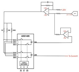
i am using the part opa2188 opamp for designing a howland current source.

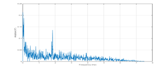
After testing current source circuit, noise is above limits. Since we need to generate 10uA. But in 10uA, .02uA variation found as noise. since we using this current source for exciting RTD sensors, it will cause error in measurement of temperature set up too. So we need to decrease noise in circuit. Can you suggest any other op amp which is less noisy. or any good techniques to reduce noise in current source? Or please suggest a good circuit with capable of generating 10uA with max 1nA noise as variation in it.

  • Hi Savi,

    please post a schematic and tell more about your application.

    A common mistake is to run a chooper OPAmp like the OPA2188 with too high ohmic feedback resistors. Some well positioned low pass filtering would be needed to reduce the noise. Also, both inputs of OPAmp should see exactly the same source impedances.

    Kai

  • pls find circuit as above. Resistor placed are 5k and ADG1409 used for range selection of current sources. To current + will go sensor excitation end.

    Also, both inputs of OPAmp should see exactly the same source impedances.

    Can explain above quote with more details.

    Also currently , we are in prototyping stage and moving on to product design. So if you suggest a new opamp also helpful.

    Application:

    we developing a temperature monitoring system for connecting sensors like 

    Glass Platinum RTD , silicon diodes ...etc .this is for cryogenics machines system monitoring. To excite this sensor, 10uA current is needed and so it should be noise free. Since noise in current will taken as measurement reading variations which will finally affect temperature readings. 

  • Adding to Kai comments, in order to eliminate the noise generated by IB spikes across the input resistors and offset shift caused by large unmatched input impedances in chopper amplifiers like OPA2188, please use instead one of the linear op amps like OPA2191 or OPA2192.

  • While comparing with OPA2191 vs OPA2188, noise density parameters is not good in OPA2191. Can you tell whether it is a good choice. since we are trying reduce noise in circuit. Especially noise frequency below 10Hz.

  • OPA2192 broadband input voltage noise density is about 5nV/rt-Hz but if you need a lowest noise at 10Hz OPA2205 may be a better choice even though its input current noise is higher due to using bipolar input transistors. Only zero-drift amplifier have no 1/f noise - in this case please take a look at OPA2182.

  • Hi Savi,

    if low frequency noise is such an enemy in your application, have you considered to provide AC biasing of the RTD sensors (in the 100Hz range) and to use a lock-in amplifier? This would solve all low frequency noise and offset voltage issues.

    Kai

  • Hi ,

    i am new to RTD biasing. Shall we use same circuit for setup ac current source as above post? or can u suggest a circuit for AC biasing of the RTD sensors. Regarding lock in amplifier, we are planning to implement in firmware. is that a good idea?

  • Hi Savi,

    there's no simple answer. The "lock-in" technique is used when your wished signal is so small that it totally dissapears in noise and other concepts would fail. But you have to pay a price when using the "lock-in" amplifer. The circuit is way more complex. To recover the signal from the noise you have to use a "synchronous detector" (see below) in combination with a "post filter". Because of the many more components in the signal chain of the "lock-in" amplifier the precision may suffer and the time constant of "post-filter" will limit your settling time after a step change of resistance of RTD.

    So you will not use the "lock-in" in any case but only if you have to because of too big noise and/or too small signal.

    Kai 

  • please find fourier transform of ADC output data samples. That 2Hz frequency causes variation in measurement. Hardware lock in implementation seems to be more complex. also our signal level not too small. So we are looking for some other suggestions other than lock amplifier.

  • Hi Savi,

    are you sure that the 2Hz noise peak is real? It looks more like "aliasing". Increase the bandwidth of your measurement and I'm sure the peak will wander to higher frequencies.

    Kai

  • It's been a week since last reply.  Thus, I'll close the post for now.