This thread has been locked.

If you have a related question, please click the "Ask a related question" button in the top right corner. The newly created question will be automatically linked to this question.

LM393: Schematic circuit verification.

Part Number: LM393
Other Parts Discussed in Thread: LM358, OPA615

Hi community,

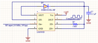
I am looking for designing an envelope detector circuit using LM393D. Since the IC has dual op-amps I would like to utilize one op-amp as a buffer input whereas another opamp as a comparator output. 

I designed the following schematic circuit but not sure if it meets the purpose since the input oscillating RF frequency amplitude is high (20Vpp) and also I am trying to operate LM393D in a single input mode with Vcc=3.6V.

I appreciate your support.
Thank you for your time and consideration in advance.

Best regards,

  • Hello Aaditya,

    The LM393 is a dual comparator - not an op-amp.

    The LM393 or LM358 are NOT fast enough for 10MHz - neither of these devices are fast enough. 100kHz maybe at best...

    In short - No. I assume the input signal is 20Vpp, which means -10 to +10V around ground. This grossly violates the negative input voltage range of -0.2V. The input signal will need to be attenuated and level-shifted to fit into the valid input range. The negative half of the cycle will be clamped and distort the signal.

    The support teams for these devices are on holiday today, and will respond when they return. This is not a simple circuit..

  • Hi Aaditya,

    this thread may interest you. See also my links given there:

    https://e2e.ti.com/support/amplifiers-group/amplifiers/f/amplifiers-forum/997908/high-speed-peak-detector

    An envelope detector can be fabricated by combining a peak detector with a suited discharging resistor in parallel to the sampling capacitor.

    Kai

  • Thank you Paul and Kai for your valuable suggestions.

    I agree with Paul regarding bandwidth and the input voltage.

    Going through the thread suggested by Kai, I found that OPA615 would be a good choice but it requires a supply voltage of +-5V. Indeed, I prefer using a single supply voltage of 3.6V so that I don't need extra power management circuits. 

    Furthermore, I am also looking for dual op-amp IC wherein I can use one of them as an input buffer and the next as a comparator.

    If there are any alternatives to this requirement, I would be happy to hear back from you.

    Thanks a lot.

    Best regards,

  • Hi all,

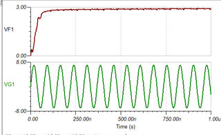
    I recently found a new IC OPAx863A with dual op-amp and I tried to design the peak detector circuit as below but I am struggling to obtain a peak amplitude.
    Can anyone help me to resolve the issue? 
    Kindly note that I would like to operate this IC in a single supply mode of Vcc = 3.3V.

    OPA2863 simulation.TSC

    Best regards,

  • Hello Aaditya,

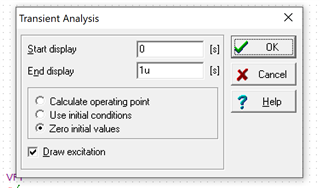
    For your simulation, you must check the "Zero Initial Values" in the simulation pop-up. This forces the simulator to actually calculate all start-up voltages  and not make a "guesstimate".

  • Dear Paul,

    Thank you. Your suggestion worked and I somehow optimized the circuit to best match my requirement.

    I have one more concern, since I am operating the IC with 3.3V, I am wondering if I need to add an additional comparator circuit before ADC!

    Thank you.

    Best regards,

  • Hi Aaditya,

    your input signal is way too large and you will destroy the OPAmp because your input signal massively exceeds the supply voltages of OPAmp. You will need to add a voltage divider at the input.

    Running this circuit with a single supply voltage has many disadvantages. Because your input signal is AC you will need some AC coupling which introduces an additional and unwanted time constant of AC the high pass filter which can make issues when the input signal amplitude is quickly changing. Then you must wait for this time constant before the amplitude is becoming constant.

    Another disadvantage is that you need a pseudo ground at middsupply to allow the circuit to properly handle the negative half waves. Later in the signal chain you have to subtract this pseudo ground again. Because of all the hassle introduced by using a single supply voltage I would run the OPAmp with a bipolar supply voltage which provides a so helpful true signal ground.

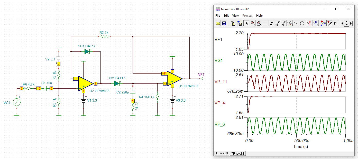
    If you insist in using a single supply voltage, you could do it this way:

    aaditya_opa2863.TSC

    By the way, what do you need the comparator for?

    Kai