Because of the Thanksgiving holiday in the U.S., TI E2E™ design support forum responses may be delayed from November 25 through December 2. Thank you for your patience.

This thread has been locked.

If you have a related question, please click the "Ask a related question" button in the top right corner. The newly created question will be automatically linked to this question.

ISO124: Output ripple

Part Number: ISO124
Other Parts Discussed in Thread: ISO224

Hi Team,

As shown on datasheet Figure 14 and Figure 15, Output Filter can improve the output ripple but this may also slow down the output so I don't want to use filters.

In my case of Input 4 V,  output 4 V, there is usually no ripple on the rise.

But I found a case with ripple in the rising waveform and the ripple disappeared after replacement of parts.

Is it due to the variations of parts? Different by lot?

Best Regards,
Tom

  • Hi Tom,

    Can you please identify what the yellow vs. pink traces are with regards to the ISO124?  The pink trace looks like an overshoot situation rather than ripple.

  • Hi Tom,

    Sorry for my mistake, It should be overshoot. 

    The Yellow waveform is the actual current waveform using the output of the current command.

    The waveform which I sent the other day is the output of 6 A in 4 V command, but the output of the insulation amplifier is not affected at this time.

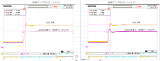
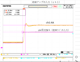
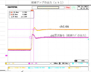
    However, when the input of the insulating amplifier is 4.76 V (peach) input, the output current is 4 A (yellow) output, but the overshoot of the output of the isolated amplifier will cause overshoot to the current. (The Yellow waveform below)

    Best Regards,
    Tom

  • So the pink trace is the input to the ISO124?  Can you get a screen shot that just shows the analog input and output of the ISO224, without the sensor?  Can you provide a schematic?  What voltages are on the supply pins of the ISO124?

  • Hi Tom,

    The pink color of the upper waveform is the input of ISO124.
    The pink color of the waveform below is the output of 1SO124.
    You can see that there is an overshoot in the output.
    *The yellow waveform is the actual current using the current command, but it is affected by the overshoot of the current command.

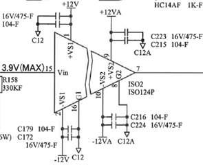
    I can't provide the details of the circuit, but as you can see below, the input of the ISO124 is used at 3.9Vmax,
    the power supply on the primary side is ±12V, the voltage on the secondary side is ±12V (separate power supply), the power supply drops, etc. there is no.
    When I replaced ISO124 with another one, the overshoot on the secondary side disappeared.

    Best Regards,
    Tom

  • Hi Liu Yang,

    If you look at figures 14 and 15 in the ISO124 datasheet, you can see the effects of the 'standard ISO124' step response - it is not uncommon to see some overshoot in the output.  The figure in the datasheet looks very similar to what you show here.  Figure 15 shows the output with the filter, the rise and fall times are @10uS with a 2V input step.  Is this a new design or have you had this in production for some time now?  What you are seeing could be variation from lot-to-lot devices.

  • Hi Tom,

    Figure 15 shows the output with the filter, the rise and fall times are @10uS with a 2V input step.  Is this a new design or have you had this in production for some time now? 
     
    I have been using it since 2012, and I have used about 1200 of the same product.
    I don't often see the output waveform of ISO124, but since there was an overshoot in the current this time,
    I found out that there was an overshoot in the output of ISO124 and it was affected by it.
     
    If the lot is the same as the lot of the device without overshoot, will it be the one without overshoot?

    Best Regards,
    Liu Yang


  • Hi Liu Yang,

    Did you try re-installing the overshoot chip?  If so, does it still overshoot?  Is it only one device you have issues with?

  • Hi Liu,

    as the output overshot is seeming normal I would add some low pass filtering to the output of ISO124. This also enhances the isolation mode rejection at high frequencies. Even only a first order RC low pass filter may do. Experiment a bit with the corner frequency of low pass filtering.

    Kai

  • Hi Tom,

    After replacing the overshooting ISO124, the overshoot disappeared.
    It has not been confirmed whether there was an overshoot in the past ones.
    Recently, when I used 20 ISO124s and checked the output current at the final stage, there was no overshoot. Therefore, it seems that there is no overshoot of ISO124.

    Best Regards,
    Liu Yang