This thread has been locked.

If you have a related question, please click the "Ask a related question" button in the top right corner. The newly created question will be automatically linked to this question.

PGA, +/-10V output, attenuation down to 0.1

Other Parts Discussed in Thread: DAC11001A, PGA202, PGA103, PGA280, PGA281, OPA4182, OPA4191, OPA1604

I am looking for a PGA for the output from DAC11001A to be able to output up to +/-10V, but also take a 5V output down to 0.5V.  Do you have any devices that would do this?  Or another suggestion on how to accomplish this?  Thank you

  • Hi KB,

    one method is to provide a hardware wired division by a factor of 10 directly behind the DAC, followed by a PGA providing the wanted gain.

    What gain / attenuation factors do you want to accomplish?

    Kai

  • Thank you for your response Kai.  Ultimately, my goal is to be able change my output ranges between +/-0.5V, +/- 1V, +/- 5V and +/-10V.  The output from the DAC is +/-5V, so I need gain/attenuation capabilities of 0.1, 0.2, 1 and 2.  My only issue with the hardware wired version is that in order to get division by 10, I'd have to use an inverting amp--or are you saying use 2 PGAs, one hard-wired, one adjustable?

  • Hi KB,

    Unfortunately we do not have a PGA that can output +/-10V with your desired gains. PGA103 and PGA202 have 36V supplies but their gain settings are somewhat limited and they cannot attenuate. PGA280/PGA281 have more flexible gain settings but will require an additional gain stage at the output to achieve the +/-10V output swing.

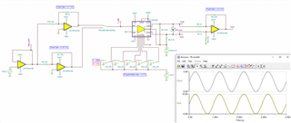
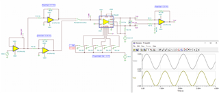
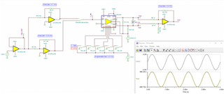
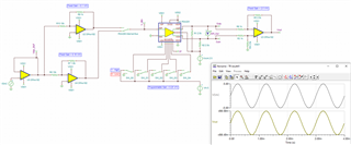
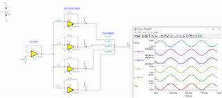
    Kai's suggestion to attenuate up front is likely the best option, however with your unbuffered DAC output this will require an additional buffer stage as well. How flexible are your gain settings? What is your bandwidth requirement? I can see a solution using a quad amp and making use of the PGA280 internal multiplexer that will meet the specified gain and output requirements. Below I included a simplified TINA simulation for proof of this concept using the PGA281 TINA spice model and the OPA4182.

    DAC_PGA_10V_output.TSC

    Regards,

    Zach

  • Hi Zach--thank you for your reply.  I was trying to find a solution that minimized the number (and size) of parts required--I need 6 copies of the final circuit on a FMC PCB--but it looks like I don't have too many options.  The only flexibility I really have with the gain is to change the ref voltage to the DAC.  In regards to bandwidth, we typically need to output DC - ~3kHz.  Do you have something similar to the PGA280 that has a SPI or I2C interface?  Otherwise I will need 30 GPIOs to set the gain on 6 PGAs.

  • Hi KB,

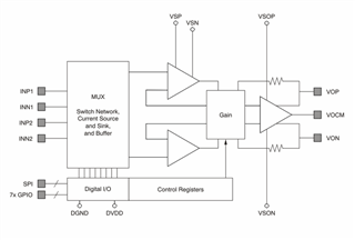
    The PGA280 does have the SPI interface as well as an internal multiplexer. The PGA281 is essentially the same device, but using a digital interface and no multiplexer. I used the PGA281 model in the simulation as the AC and DC performance is functionally equivalent to the PGA280. See the PGA280 block diagram below.

    If size is a concern, I recommend the OPA4191 as your quad amp as this is available in the 4mm x 4mm WQFN package.

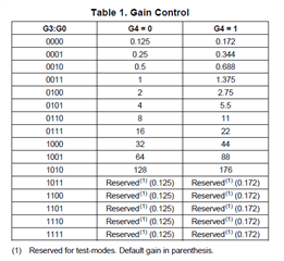
    The PGA280 has binary gains from 1/8 V/V to 128 V/V, as well as an optional gain factor of 1.375. Depending on how tight your gain requirements are and/or if you can slightly adjust your gain through the DAC reference voltage, you may be able to omit one of the input attenuating amps and reduce to a 3 amp + PGA solution.

    Regards,

    Zach

  • KB,

    As you only require four specific gain settings, the simplest and smallest solution here may be to simply use a buffer along with a quad amp and an output multiplexer to select the gain. This will simplify the design and give you more options to select small package devices.

    DAC_4Gain_mux_output.TSC

    Regards,

    Zach

  • Zach,

    I really like that idea--my only problem is that the output will be inverted, so I'd have to add another device between the gain stage and the mux.  The other thing I like about using the PGA is that the gain is more flexible.  The system I'm working on is relatively experimental and frequently requirements change.  That being said, I can only predict the future so much  Slight smile.  You have given me food for thought and I very much appreciate your help.

  • Hi KB,

    Have you considered resolving the inversion digitally? You may be able to use processing to invert the polarity of your digital code before sending it to your DAC.

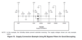
    The PGA solution will likely be larger and more complex, although it does provide the most flexible gain options. Do consider that the PGA280 requires multiple power supplies with decoupling capacitors, Schottky protection diodes, and current-limiting resistors that will add to the overall solution size.

    Let me know if you have any further questions and good luck with your design.

    Regards,

    Zach

  • Zach,

    I have considered inverting the input code, but this board is used for so many functions that I don't want to possibly confuse anything.  It's not out of the question, though--I will toss the idea around to the stakeholders and see what they think.  Weighing the 2 options, I do agree that the version without the PGA is a better one for this situation--and there is such a spread of gains that those utilizing this board should be able to find one of the 4 options that works for their use case.

    Thanks again for your help!

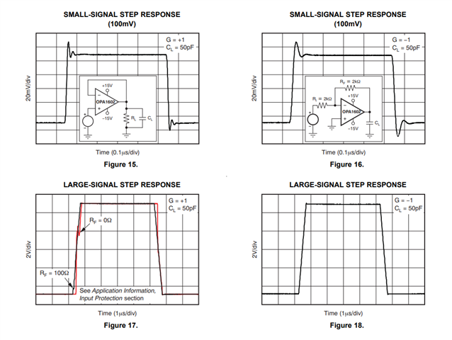
  • Oh I did want to mention also that I think I'm going to go with the OPA1604 part--it seems to have better noise performance and the TSSOP "should" fit within the size constraints--especially if I don't wind up requiring the inverting stage.  My one question about the part is what is the settling time?  It doesn't mention that anywhere in the data sheet (that I could find).

  • Hi KB,

    The settling time is a function of the slew rate and the small-signal bandwidth. A lot of older parts do not have a specification for settling time, although the OPA1604 datasheet does show small-signal and large-signal step response in the typical characteristics section. There is also a TINA model for the OPA160x which can be used to simulate settling time based on the slew rate and bandwidth parameters.

    sbomas6b (1).tsc

    Regards,

    Zach