This thread has been locked.

If you have a related question, please click the "Ask a related question" button in the top right corner. The newly created question will be automatically linked to this question.

LMP7701: plot in PSpice impedance vs frequency

Part Number: LMP7701
Other Parts Discussed in Thread: TINA-TI

Hi Team, 

Good day. I am posting this inquiry on behalf of our customer.

"I am using Pspice. I want to plot the input and output impedance of opamp. I have connected one AC source to the opamp. How to plot in PSpice impedance vs frequency

I have added bootstrapping at the input of Opamp."

Please help to advise. Thank you for extending your support.

Kind regards, 

Marvin

  • Hi Marvin,

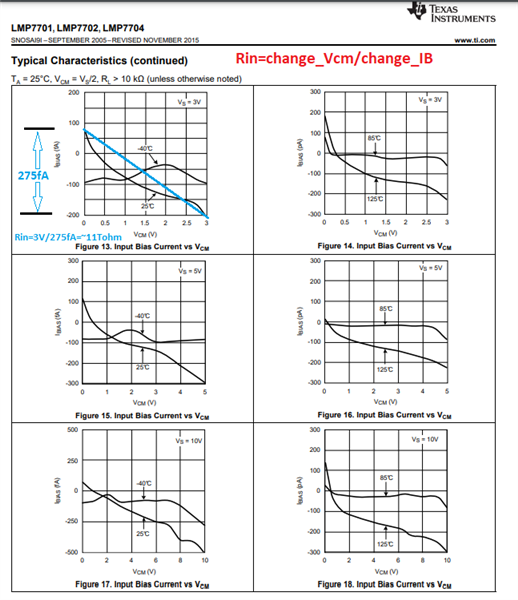
    The resistive part of the LMP7701 input impedance, Rin, may be calculated under different conditions from the graphs of the change of the IB vs Vcm - see 11Tohm example below.

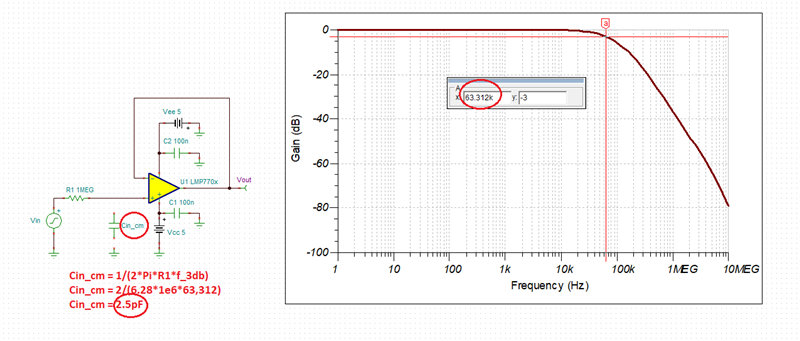
    The LMP7701 input common-mode capacitance (Cin_cm) may be simulated and then back-calculated as shown below to be 2.5pF.

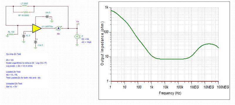
    The output impedance (Zo) may be simulated as shown below.

    Below I have attached Tina-TI simulation files for your convenience.

    LMP7701 Rin_cm.TSC

    LMP7701 Zo.TSC