Because of the holidays, TI E2E™ design support forum responses will be delayed from Dec. 25 through Jan. 2. Thank you for your patience.

This thread has been locked.

If you have a related question, please click the "Ask a related question" button in the top right corner. The newly created question will be automatically linked to this question.

INA234: INA2134

Part Number: INA234

Hi 

I am using 4 INA234 in my design on the same i2c bus. cant get logical reads from shunt voltage, power and current register that will make sense with external power supply measurement. 

for :

20mohm shunt register assembled on board

MAX current 0.75A 

Current threshold 0.7A 

we calculated 1000h for the calibration register

we read:

shunt voltage register [1h] 0280h

bus voltage register [2h] 03c0h - from calculation we get 1.536V - good result

power register [3h] 0168h

current register [4h]  1d10

we measure:

bus voltage = 1.6V

current = 457mA

please explain how to translate the reads to get the measured current. 


regards

Neli Janssen

  • Neli,

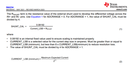
    For a maximum current of 0.75A, I calculate the calibration register = (211 * 0.08192)/(0.75A*20mΩ) = 0x2bb0 for the smallest ADC range by combining equations 1 and 2 from the datasheet below. Your readings still don't make much sense to me, but perhaps you can try to retake your measurements with the new configuration values and we will see if the new data makes more sense.

    Levi DeVries

  • Hi Levi 

    I got the value for 0x1000 for calibration register, when rounding up equation 2 (to 0.001) - with the limitation of no higher than 8X.

    without rounding I get 0x2bb1 - so for this value

    I see 0.7mA from PS screen , I received 0x0020 at the current register - this is good.

    my question now - what is the meaning of minimum detected current if I can measur 0.7mA ?

    in my case 100uV/20mOhm = 5mA  is the minimum detected current 

    thanks

    Neli 

  • Neli,

    I think you may be using the formulas wrong based on your numbers. In order to get the real-world values from the register values you must multiply the register value by the LSB (least significant bit) for that value. The Vshunt LSB value for the INA234 will always be 10 or 40 mV depending on the ADC range settings you are using. The Vbus LSB will always be 25.6mV, and the current LSB is calculated from value of the maximum current you wish to measure using formula 2 above.

    If you use 0x2bb1 as your calibration value the current LSB will be 366uA, so in your example for a current register value of 0x0020 the real-world current will be 11.72mA.

    As a note, the Calibration value is calculated using formula 1 above from the current LSB and the Rshunt value.

    Please let me know if you still have questions,

    Levi DeVries

  • Hi Levi 

    I understand the calculations for the real-world values from the register values, except the current.

    in table 8-4 from the data sheet - you can see that in order to calculate the current value, you need to right shift the register value.

    this is why in my calculation when I read 0x0020 I multiplied the Current_LSB in 2. 

    In your calculation you multiplied in 32, I guess based on eq-3

    that the contradiction between our calculations.

    0.7mA is the my real current consumption - so I am asking 

    what is the minimum detected current ?  100uV/20mOhm = 5mA  ?

    thanks

    Neli 

  • Neli,

    I believe I understand your question now, sorry for my confusion, I was unaware of how this device stored the current result- you are correct that the current register must be shifted to the right by 4 bits.

    The 100µV figure is the maximum offset error voltage that may be read by the device, so 5mA is a measure of the inaccuracy of the reading. The resolution of the current register (based on the LSB which I was explaining above) allows you to read a value smaller than the error specification, but it could be an erroneous result due to the offset error of the device.

    Because of the offset error your application will always have a ±5mA offset with a 20mΩ shunt. The error is a larger issue if you are planning to measure small currents. This can be minimized by using a larger shunt resistor (resulting in larger voltages across the shunt) or by using an amplifier with a smaller offset voltage than the INA234.

    A good resource for calculating the error of this chip in different configurations and comparing this device's error to different chips is found here: https://www.ti.com/tool/CS-AMPLIFIER-ERROR-TOOL 

    Let me know if you have any more questions regarding this issue,

    Levi DeVries