This thread has been locked.

If you have a related question, please click the "Ask a related question" button in the top right corner. The newly created question will be automatically linked to this question.

LMH32401: LMH32401

Part Number: LMH32401
Other Parts Discussed in Thread: LMH6552, , TINA-TI

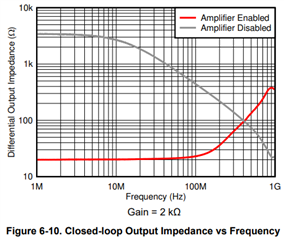
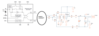
I want to connect the LMH32401 DIFF outputs to LMH6552 configured as a differential amplifier with a gain of two. 

input resistor is 100 ohm and the feedback resistor is 200 ohm.

How to do it?

See schematics:

Thanks,

Giora

  • Hi Giora,

    Thank you for your question. The LMH32401 is a integrated TIA with fully differential outputs that would allow you to drive an ADC without an additional FDA.

    To use it with the additional FDA of the LMH6552, you can connect the outputs directly to the input of the LMH6552 by connecting the negative output of the LMH32401 to the negative input of the LMH6552 and the same with the positive terminals.

    Additionally, we have TINA-TI models and reference circuits to help you with your design process by simulating the circuit response. 

    Thank you,
    Rachel

  • Hi Rachei,

    Thanks.

    No need to put a parallel resistor between the positive and negative outputs of the LMH32401 so the total parallel impedance of this resistor

    and the input impedance of the FDA (with 100 ohms resistors connected to the plus and minus inputs)?

    Sincerely,

    Giora

  • Hi Giora,

    Thank you for the additional clarification on your question. What you put on the output of the transimpedance amplifier depends on the overall gain and signal response you are looking for within your system, as well as the system inputs (for example, the input capacitance from the photodiode being used).

    However in general, an additional resistor between the outputs is not required for the performance of the device independently. 

    Attached is an example circuit from TINA-TI that you can adjust to help simulate the behavior of your system.
    LMH32401 and LMH6552.TSC

    You can also review the graph below, close-loop output impedance vs. frequency. This graph demonstrates the impedance as seen on the output of the amplifier across frequency while the device is enabled and disabled, to help make any additional determinations.

    Thank you,
    Rachel

  • Rachel,

    Thanks.

    Will try.

    Regards,

    Giora