Other Parts Discussed in Thread: OPA172, TINA-TI
Hi Team,
I want to rebuild the TIPD181 pre-amplifier. My first step was to order the TIDC916 PCB from JLCPCB. Then I assembled all parts from the TIPD181 reference design guide.
I applied a voltage of 9 V and measured at the highlighted spots of the schematic to GND. The color of the arrows matches the corresponding waveforms.
All measurements were done in AC mode (x: 100ms/div, y: 10mV/div).
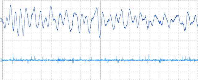
The microphone signal (darkblue) seems to be fine. But the signal is gone after the capacitor C3 (lightblue).
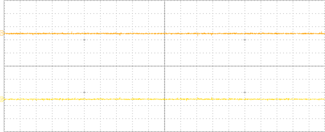
The output signal of OPA172 (orange) is about 0 mV and not the amplified input signal. It is the same at the RCA connector (yellow).
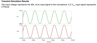
After this I found “TINA-TI Reference Design Companion for TIA Microphone Amplifier Circuit” which confused me even more. The file (SBOA291.TSC) contains a similar circuit. A transient simulation (image below) tells me that the input signal (± 2,83 V) is lower than the output signal (± 1,70 V).
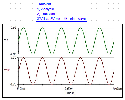
How do I amplify the microphone signal? Why is the input signal smaller than the output signal in the simulation?
I built this design now three times. It is always the same result.
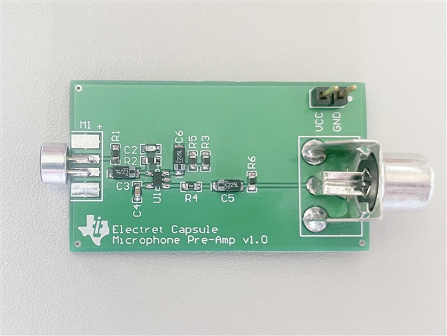
Kind Regards,
Jejomar


