This thread has been locked.

If you have a related question, please click the "Ask a related question" button in the top right corner. The newly created question will be automatically linked to this question.

LMC662: Inquiry about LMC662AIM amplification rate

Part Number: LMC662

Hi, TI expert

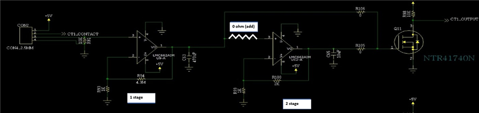
There is a problem that the amplification rate is too different while the customer is using the LMC662AIM (OPAMP).

The test was conducted with 10 samples received a few years ago. Since the samples are old parts, I think there may be a problem with the part itself, but I wonder if the circuit configuration is wrong.

- When only LMC662AIM (OPAMP) is changed in the same amplifier circuit,
: 5 out of 10 are amplified well, 5 are not amplified.
: The amplification factor of the first stage of the circuit below varies greatly depending on the IC.
(When only the LMC662AIM is replaced, the amplification rate is different and the deviation is severe.)

Please check that there is no problem with the circuit configuration below.

  • What are the input and output voltages you're measuring? The LMC662 does not have rail-to-rail inputs and requires a headroom of 2.5 V to the positive supply.

  • The customer wants to amplify the voltage through the CT circuit.
    A voltage of about 10mV comes out from the CT side, so I want the output to be about 3V or more.

  • Grady,

    I would like to ask a few questions, and point out a few items to help with your circuit.

    1. The schematic is very difficult to read.  I think I can understand at least part of the schematic, and will provide guidance based in what think the schematic says.  Is there some way you could provide a clear diagram?
    2. It appears that you have a 470uF capacitor on the output of the first stage and a 10uF on the output of the second stage.  You really shouldn't place capacitors directly on amplifier outputs.  Capacitors on the output of an op-amp cause instability.  Instability means that the output will oscillate rather than gain up signals.  We have a video series that covers this topic.  Here is the link to the entire amplifier series (Op Amp Training).  If you search through the training list you will find 7 videos on stability.  This is a pretty detailed subject, so if it is possible to simply remove the capacitors, this is the easiest option.
    3. The first amplifier appears to be in a gain of 4500 (4.5M/1k + 1 = 4501).  This is an unusually high gain.  Any circuit in this gain this high will be sensitive to any small issue.  Since the offset of the amplifier can be as high as 6mV, the offset alone can drive the output into the supply rail (6mV x 4501 = 25V).
    4. If you want to amplify a 10mV signal to 3V, you need a gain of 3V/10mV = 300.  Also, you should choose an amplifier with an input offset voltage much smaller than 10mV if you want to accurately amplify 10mV.
    5. Maybe I didn't read your schematic correctly as it is hard to see the details.
    6. The Op Amp Training is a good resource to help you ramp up your understanding on amplifiers.

    Best regards,

    Art Kay

  • Hi Art Kay

    Thank you for answer.

    We will ask again if we have further questions.