Because of the holidays, TI E2E™ design support forum responses will be delayed from Dec. 25 through Jan. 2. Thank you for your patience.

This thread has been locked.

If you have a related question, please click the "Ask a related question" button in the top right corner. The newly created question will be automatically linked to this question.

TRF37D73: Input impedance

Part Number: TRF37D73
Other Parts Discussed in Thread: OPA3S2859, OPA855, OPA858

Hello,

I am looking to use this RF gain block as the first stage in a photodetector application. I was wondering if there is a real resistor to ground from the RF input? My understanding is that this is a SiGe darlington amplifier and so I would expect there to be one but I want to confirm and be able to take measurements to confirm. 

  • Hi Michael,

        Welcome to e2e!

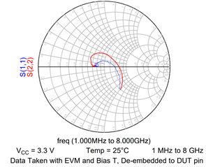
    TRF37D73 is a SiGe Darlington amplifier with integrated 50 Ω input and output matching. The device contains a proprietary active bias circuit to maintain performance over a wide temperature and voltage range. Since it is an active bias there is no physical R from RF in to ground but it is internally matched to 50 ohm. 
    Below is the smith Chart for the same:

    Regards,
    Hruday

  • Hi Hruday,

    Thanks for the welcome and thanks for the answer!

    I am using this as a TIA with a low-capacitance photodiode to detect a small signal >1 GHz. I ran some SPICE simulations and my observed gain is about 10x higher than simulation. I've seen other Darlington amplifiers used as TIAs but having trouble analyzing this due to (I think) the active bias circuitry. Any suggestions?

  • Hello Michael,

      Are you currently using the TRF37D73 as a TIA and you are seeing the gain discrepancy between simulation and in practice? If so, would you be able to share a schematic? Also, a few questions below:

    1. What is the capacitance value internal to photodiode?
    2. What is your input current range?
    3. What is your target gain?

      We can help recommend another device which is more suited for TIA applications. 

    Thanks!

    Sima 

  • Hi Sima,

    Yes, I am currently (trying) to use the TRF37D73 as a TIA. I am seeing a discrepancy between the gain that a SPICE simulation gives me and the gain that I see in the lab. I want to note that the power gain of about 20dB is observed and matches between simulation and experiment, but the transimpedance gain does not. 

    1. The capacitance is about 0.5pF at 5V reverse bias on the photodiode.

    2. This is a tricky one. The maximum current is 30mA and the minimum current is about 30nA. The 30nA signal is the signal of interest, at about 2 GHz. The 30mA current is not important but, as an aside, it is causing some problems. That's not too critical right now though, I am more interested in understanding the discrepancy between the "small signal" transimpedance gain.

    3. An overall transimpedance gain of >10k is a good starting point.

    Thanks,

    Michael

  • Hello Michael,

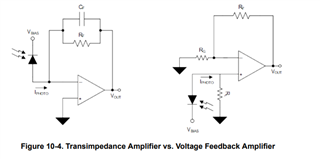
      Thank you for the additional information. I am guessing you are using a shunt resistor to convert the input current to a voltage, and then feeding that signal into the TRF37D73 due to the gain block's internal gain and lack of a feedback design. Is that correct? Below is a reference using a VFB rather than RF gain block, but similar concept:

      Also, I apologize I forgot to ask, what is your frequency range or rise time range of your input pulse?

      For the large current range, we do have an integrated TIA for gain switching. The device name is OPA3S2859; let us know if this device fits your design requirements, and feel free to ask questions about this device. 

    Best Regards,
    Sima 

  • Hi Sima,

    That was my originally idea, yes. I placed as 50R resistor to ground before the DC blocking capacitor. However, my simulation and calculations do not match the observed gain in the lab.

    The signal I am interested in amplifying is at 2 GHz and about 30nApp whereas the large amplitude 30mA should be considered more as noise.

    I do not think the device you suggested meets my requirements due to the <1GHz bandwidth,

    Thanks,

    Michael 

  • Hello Michael,

       Would you be able to share simulation/calculations and a scope shot of what you are seeing in the lab? From the TRF37D73, you should be seeing around 19.5dB of gain at around 2GHz. 

       Understood, and yes the device would not be able to meet your bandwidth requirements. For a TIA application, I would suggest looking into the OPA858 or OPA855. But, we can first look into the discrepancy you are seeing with the TRF37D73.

    Thank you,

    Sima